Power supply apparatus and power supply method
- Summary
- Abstract
- Description
- Claims
- Application Information
AI Technical Summary
Benefits of technology
Problems solved by technology
Method used
Image

Examples
first example
Configuration of Power Supply System
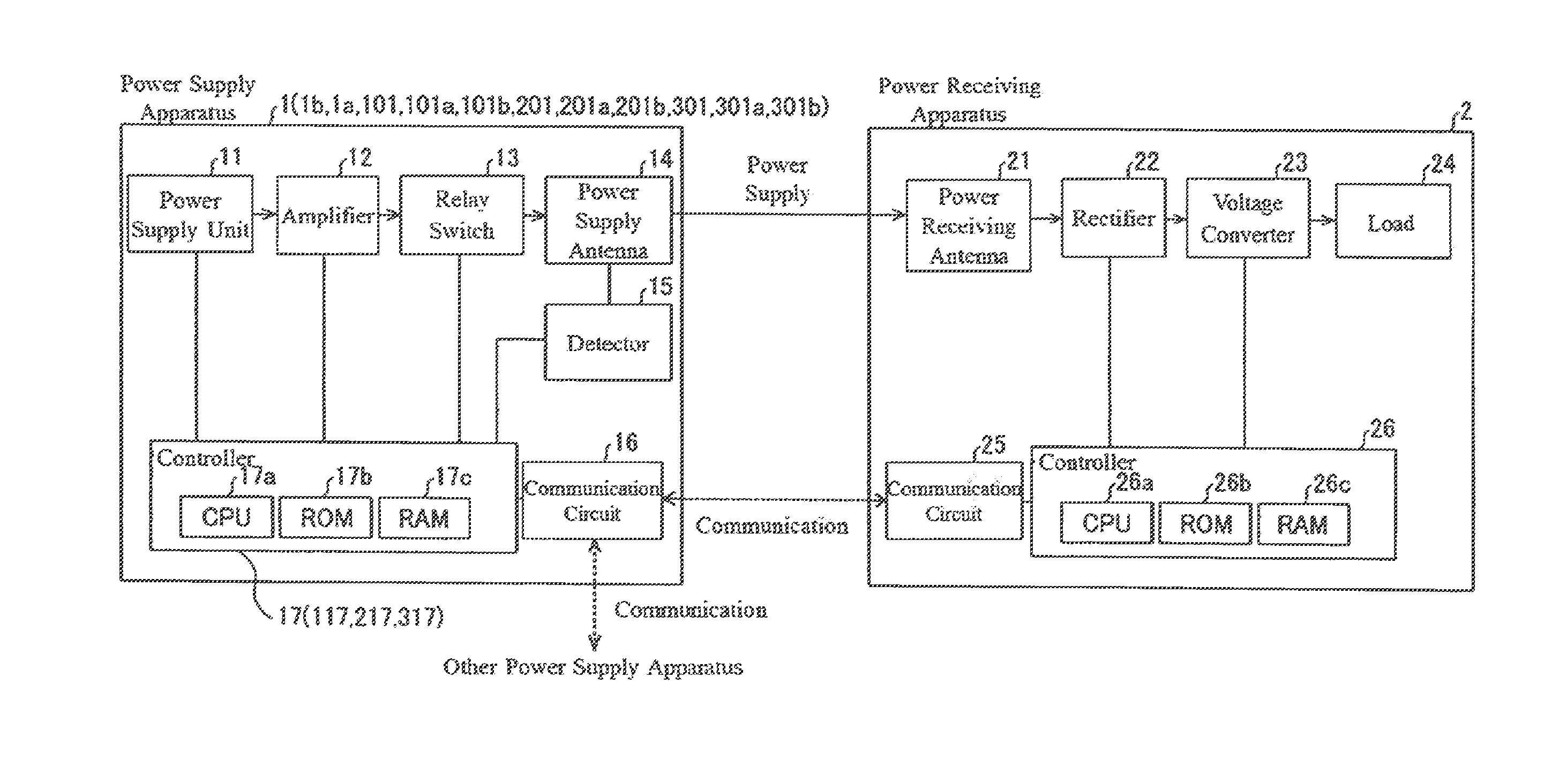
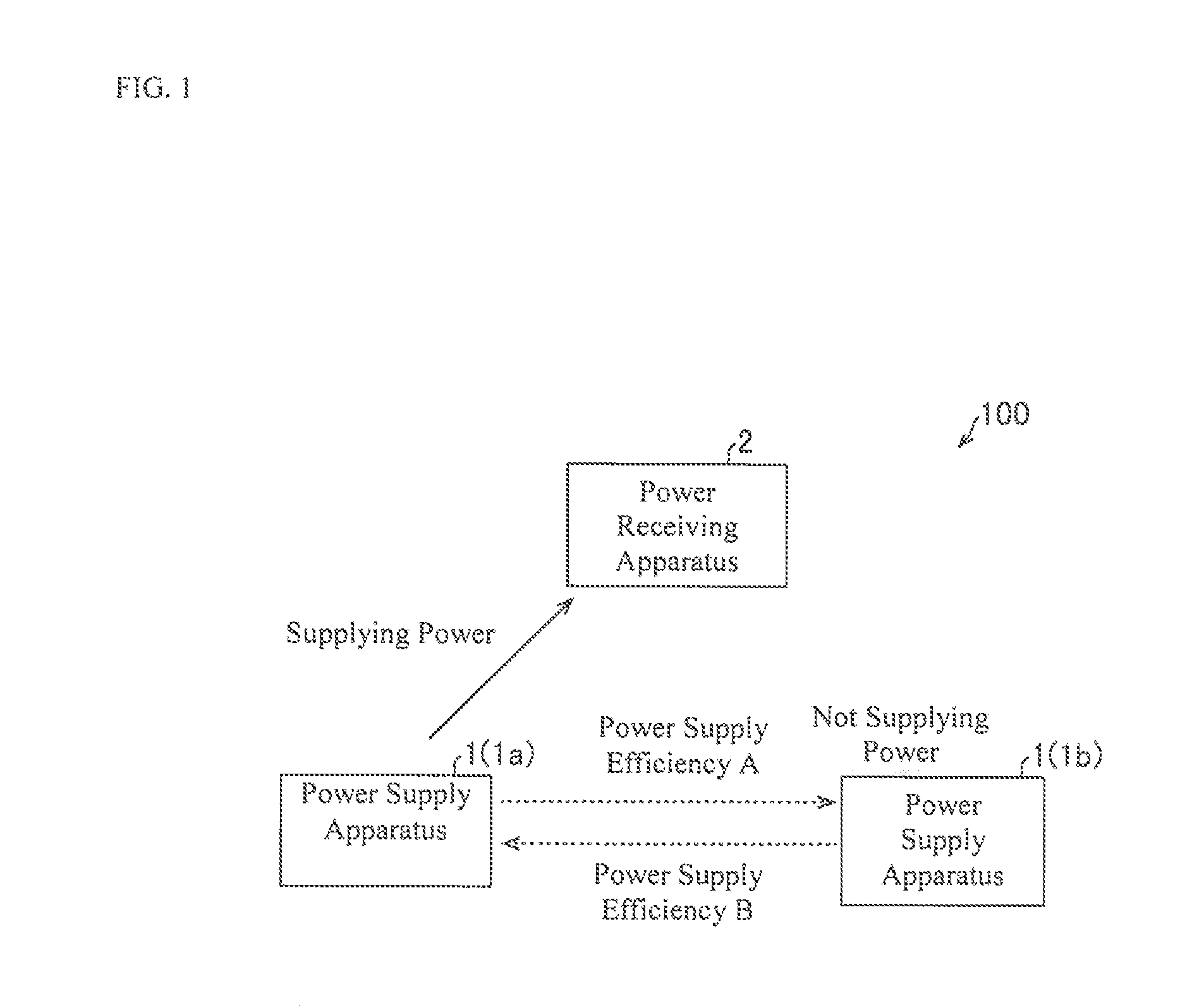
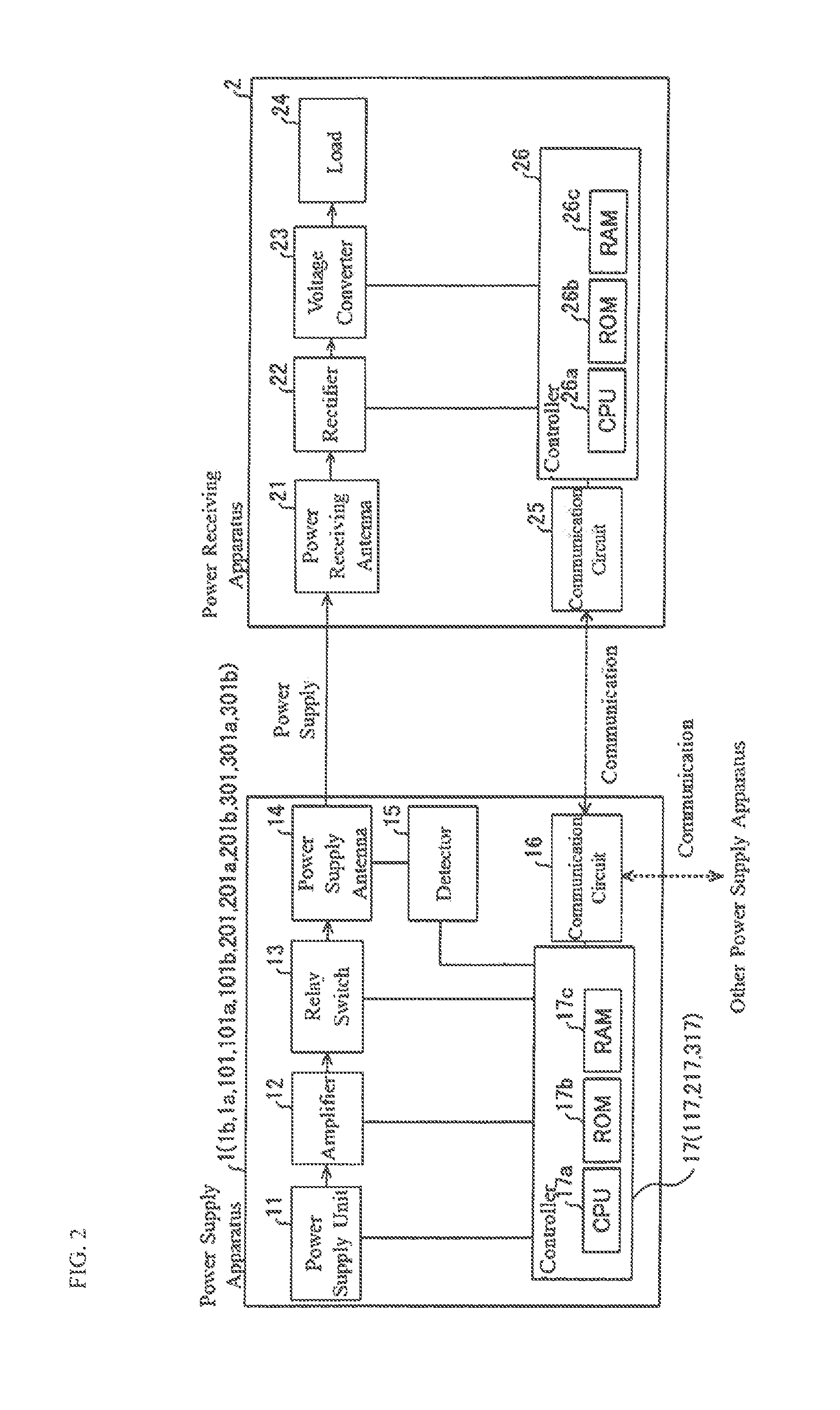
[0033]First, a configuration of the power supply system 100 according to the first example of the present invention will be described with reference to FIG. 1 and FIG. 2.
[0034]The power supply system 100 according to the first example of the present invention, as illustrated in FIG. 1, includes a plurality (two) of a power supply apparatus 1 (1a and 1b), and a power receiving apparatus 2. The power supply system 100, for example, is a non-contact method power supply system for providing power (supplying power) to the power receiving apparatus 2 from the power supply apparatus 1 without electrical contact of a connector or the like, by a magnetic field resonance method. In addition, in the power supply system 100, the plurality of power supply apparatus 1 are disposed in a position adjacent to each other. In addition, in the power supply system 100, an electronic device such as a tablet or a smart phone, for example, can be used as the power receiv...
second example
[0133]Next, embodiments of the second example of the present invention will be described with reference to FIG. 2 and FIG. 7 through FIG. 9. In one or more embodiments of the second example of the present invention, in addition to the configuration of one or more embodiments of the first example of the present invention, the power supply efficiency of the equipment itself (third value) and the power supply efficiency of another power supply apparatus (fourth value) again may be acquired at a predetermined timing while the power supply is resumed, and an example of determining whether or not the power supply efficiency of the equipment itself is larger than the power supply efficiency of the other power supply apparatus will be described.
[0134](Configuration of Power Supply System)
[0135]The power supply system 200 according to one or more embodiments of the second example of the present invention, as illustrated in FIG. 2, is different than the power supply system 100 according to on...
third example
[0155]Next, embodiments of the third example of the present invention will be described with reference to FIG. 2, FIG. 7, FIG. 10 and FIG. 11. In one or more embodiments of the third example of the present invention, in addition to the configuration of one or more embodiments of the first example of the present invention, while the power supply is resumed, the power supply efficiency of the equipment itself and the power supply efficiency of another power supply apparatus is again acquired at a predetermined timing, and another example differing from one or more embodiments of the second example of the present invention for determining whether or not the power supply efficiency of the equipment itself is larger than the power supply efficiency of the other power supply apparatus will be described.
[0156](Configuration of Power Supply System)
[0157]The power supply system 300 according to one or more embodiments of the third example of the present invention, as illustrated in FIG. 2, i...
PUM
 Abstract
Description
Claims
Application Information
 - R&D
- Intellectual Property
- Life Sciences
- Materials
- Tech Scout
- Unparalleled Data Quality
- Higher Quality Content
- 60% Fewer Hallucinations
Browse by: Latest US Patents, China's latest patents, Technical Efficacy Thesaurus, Application Domain, Technology Topic, Popular Technical Reports.
© 2025 PatSnap. All rights reserved.Legal|Privacy policy|Modern Slavery Act Transparency Statement|Sitemap|About US| Contact US: help@patsnap.com