Vector vortex waveplates

a technology of vortex wave plate and liquid crystal polymer, which is applied in the direction of instruments, polarising elements, pretreated surfaces, etc., can solve the problems of starlight and noise, and achieve the effect of wide spectral range of operation and improved optical properties

Active Publication Date: 2017-01-12
BEAM ENG FOR ADVANCED MEASUREMENTS
View PDF3 Cites 27 Cited by
  • Summary
  • Abstract
  • Description
  • Claims
  • Application Information

AI Technical Summary

Benefits of technology

The present invention aims to improve the optical properties of LCP VVWs by using materials that can reversibly photoalign, making it easier to transfer light energy from the beam's axis to its edge. This is achieved by combining multiple LCP layers into a single WW, resulting in a reduced defect size and improved performance across a wide spectral range.

Problems solved by technology

The challenge in imaging faint objects near bright stars is in reducing the starlight and the noise by many orders of magnitude while efficiently transmitting the planet light.

Method used


Image

  • Vector vortex waveplates
  • Vector vortex waveplates
  • Vector vortex waveplates

Examples


Embodiment Construction

[0013]Before explaining the disclosed embodiment of the present invention in detail it is to be understood that the invention is not limited in its application to the details of the particular arrangement shown since the invention is capable of other embodiments. Also, the terminology used herein is for the purpose of description and not limitation.

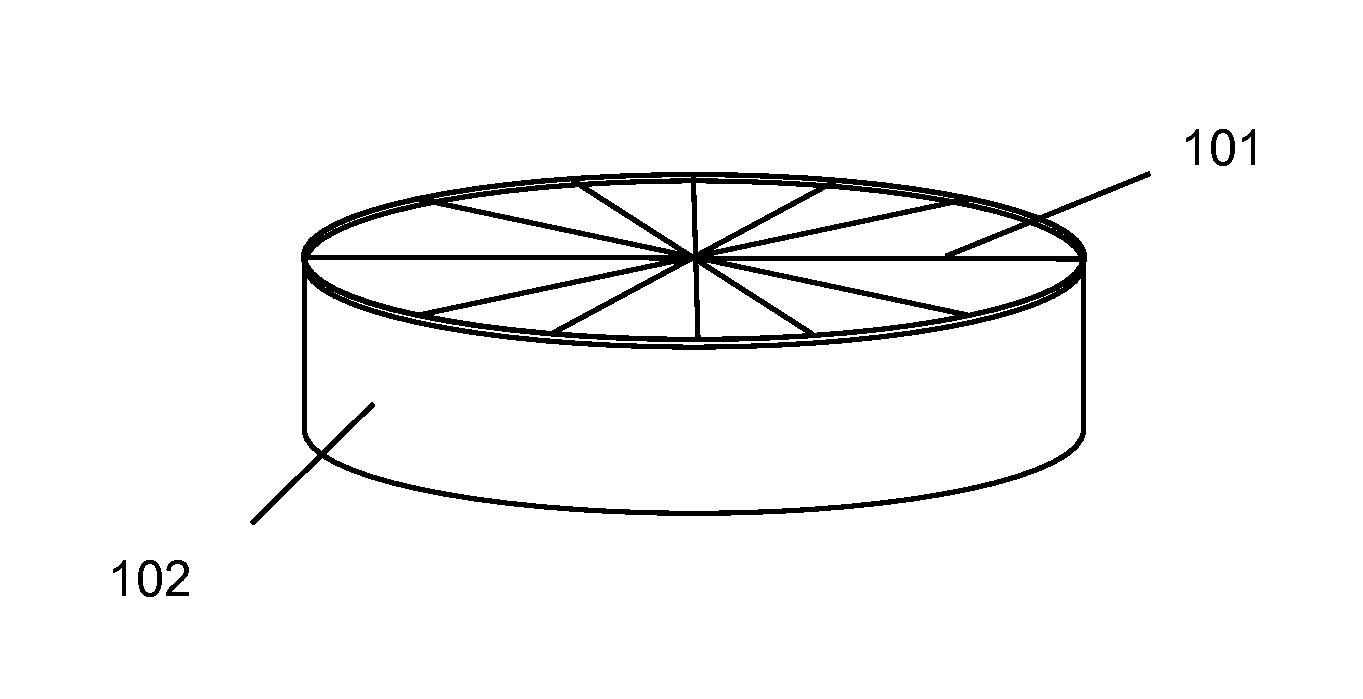
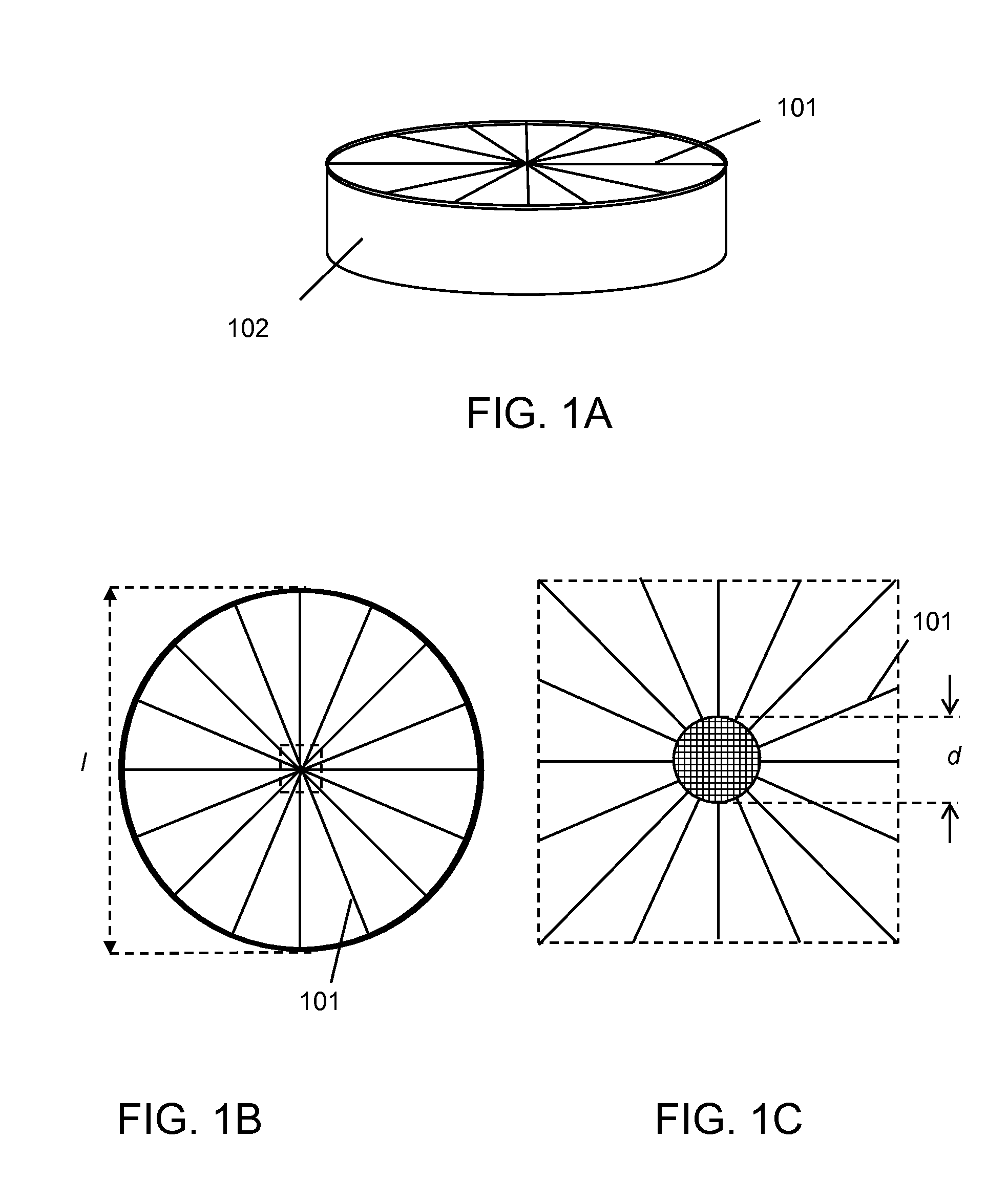
[0014]An example of a VVW is shown in FIG. 1A. It comprises a substrate 102 and the LCP layer 101 deposited on said substrate. The optical axis orientation in this example of a preferred embodiment is radially aligned as shown in FIG. 1B. The optical axis orientation is not well defined in the center of a VVW. Typically, a defect of not oriented LCP is present within the axial region of an average size indicated as d in FIG. 1C. Defect sizes as large as d˜100 micrometer were known in the earlier art. Even if the diameter of the VVW indicated as I in FIG. 1B may be much larger than the defect size d, light scattering in this region may mak...


PUM


Abstract

Method for fabrication of vector vortex waveplates of improved quality due to reduced singularity size and widened spectral band, the method comprising creating a boundary condition for vortex orientation pattern of a liquid crystal polymer on a substrate using materials with reversible photoalignment, equalizing exposure energy over the area of the waveplate by redistributing the energy of radiation used for photoalignment from the center of the beam to its peripheries, and using vector vortex waveplate as a linear-to-axial polarization converter. Fabrication of spectrally broadband vector vortex waveplates further comprises two or more liquid crystal polymer layers with opposite sign of twist.

Description

FIELD OF THE INVENTION[0001]This invention relates to fabrication of liquid crystal polymer vector vortex waveplates (VVWs) with improved optical properties due to decreased defect size, widened spectral bandwidth, and large area. VVWs are used in astronomy, imaging, optical communication, photonics and display technologies.BACKGROUND OF THE INVENTION[0002]The challenge in imaging faint objects near bright stars is in reducing the starlight and the noise by many orders of magnitude while efficiently transmitting the planet light. Due to scattered starlight, the planets near bright stars could be observed earlier only at large angular separations and with large telescopes. Using a small aperture telescope system for detecting exoplanets at nearly diffraction limit of their separation from the star can have a significant impact on astronomy as well as other imaging and space communication systems. Vector vortex coronagraphs prove to provide such an opportunity. When used with larger a...

Claims


Application Information

Patent Timeline
Patent Type & Authority Applications(United States)
IPC IPC(8): G02B5/30B05D3/06B05D5/06
CPCG02B5/3016B05D3/06B05D5/06
Inventor TABIRIAN, NELSONNERSISYAN, SARIK
Owner BEAM ENG FOR ADVANCED MEASUREMENTS
Why Eureka
Try Eureka