
Housing for driving an apparatus for a turbine engine

a technology for turbine engines and gearboxes, which is applied in mechanical equipment, machines/engines, and gearboxes. it can solve the problems of power take-off and inability to achieve on all shafts of turbine engines

Active Publication Date: 2017-01-12
SAFRAN TRANSMISSION SYST
View PDF2 Cites 6 Cited by
  • Summary
  • Abstract
  • Description
  • Claims
  • Application Information

AI Technical Summary

Benefits of technology

The invention is a gearbox that can be attached to a turbine machine to power external devices. It offers more flexibility in where the power takes off, either on the high-pressure shaft of the turbine, the low-pressure shaft, or the intermediate shaft. The gearbox uses a central shaft and a set of gears to transmit the power from the turbine machine to the external device. This setup saves space and allows for more flexibility in how the gearbox is positioned.

Problems solved by technology

In these two documents, however, the power take-off is constrained and it cannot be achieved on all the shafts of the turbine engine.

Method used


Image

  • Housing for driving an apparatus for a turbine engine
  • Housing for driving an apparatus for a turbine engine
  • Housing for driving an apparatus for a turbine engine

Examples


first embodiment

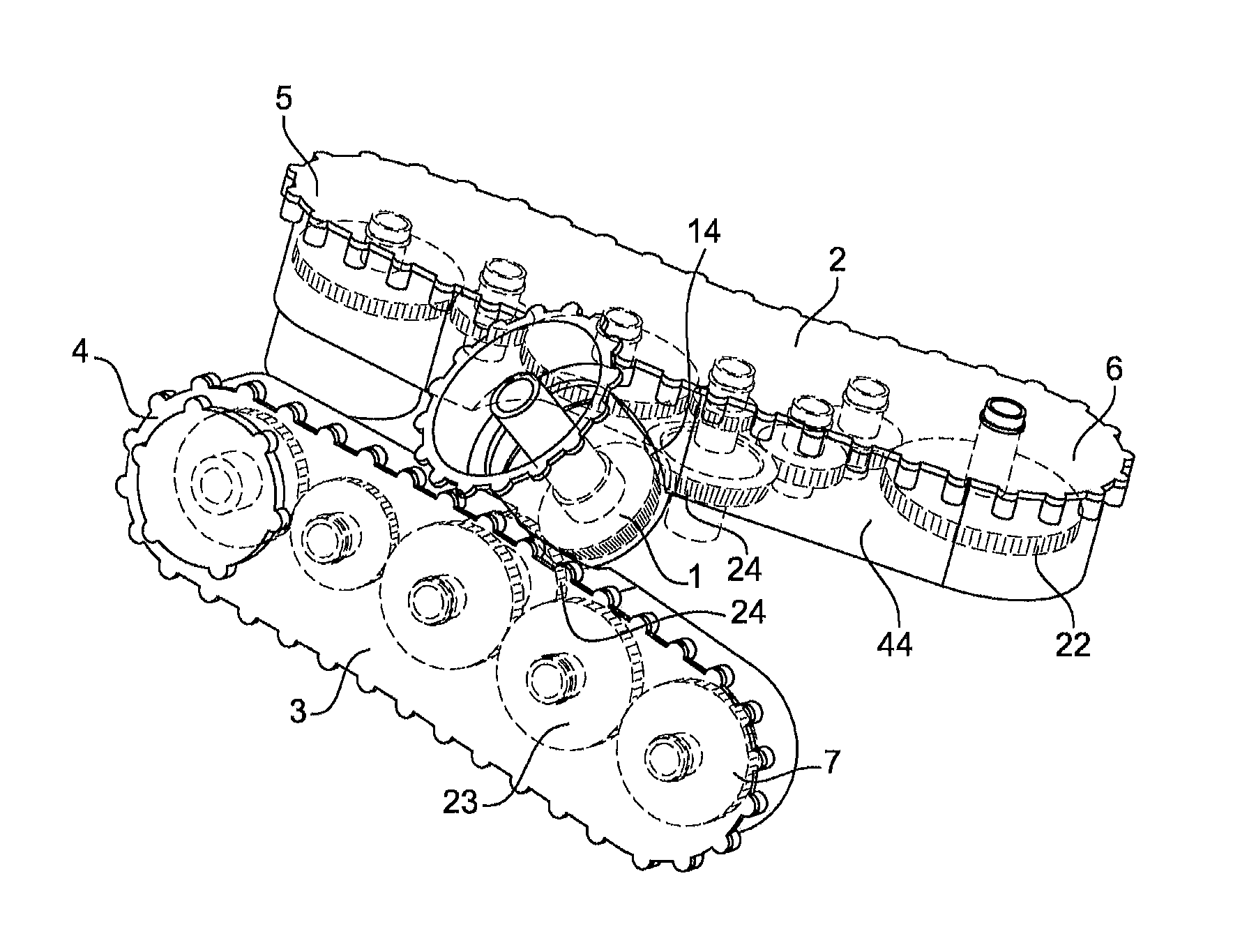
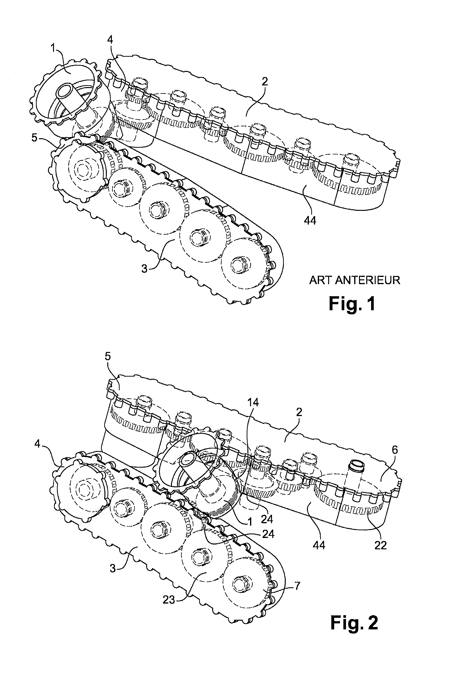
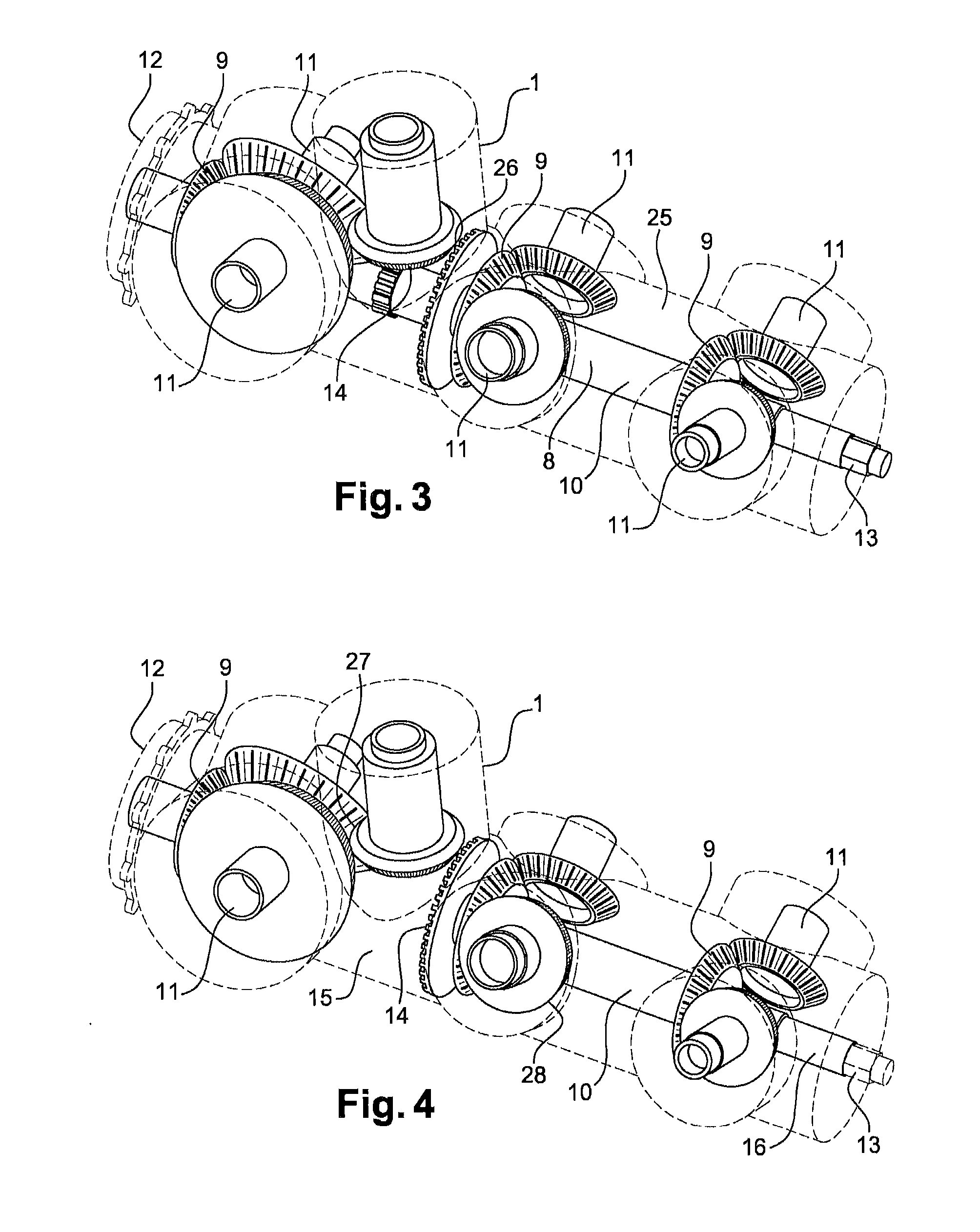
[0018] known as “column gearbox”, the kinematic chain comprises at least one central shaft capable of transmitting the movement of the power take-off member to at least one rotatable shaft of an apparatus through at least one intermediate gear, where the central shaft comprises two ends, the power take-off member being linked to the central shaft by a gear having convergent axes located between the first end and the second end of the central shaft. Thus in this embodiment, the movement of the power take-off member is transmitted to the rotatable shaft of the apparatus through a central shaft, which saves space and allows greater latitude in the layout of the gearbox.

[0019]Advantageously, the power take-off member extends along a direction which forms a secant with that of the central shaft.

[0020]Advantageously the central shaft comprises a first and second part, with the power take-off member being linked to the first part by a first gear with convergent axes and to the second part ...

second embodiment

[0022] known as a “V gearbox”, the gearbox comprises two kinematic chains, each kinematic chain being capable of transmitting the rotation movement of the power take-off member to at least one rotatable shaft of an apparatus, each kinematic chain comprising a first end and a second end, the power take-off member being linked to each kinematic chain by a gear having convergent axes located between the first and the second end of each kinematic chain.

[0023]Advantageously, each kinematic chain comprises a gear train, with the two gear trains extending along directions forming a secant.

[0024]According to different embodiments, the two gears having convergent axes may exhibit reduction ratios which are different or which are equal.

[0025]A second aspect of the invention relates to a turbine engine comprising a gearbox according to one of the preceding claims.

[0026]According to different embodiments:[0027]the turbine engine comprises a high-pressure shaft, with the power take-off member be...


PUM


Abstract

A gearbox to be attached to a turbine engine to drive at least one apparatus annexed to the turbine engine, the gearbox including a housing; a power take-off member capable of engaging with a radial shaft of the turbine engine; at least one kinematic chain located inside the housing and capable of transmitting the rotational movement of the power take-off member to at least one rotatable shaft of an apparatus. The kinematic chain includes a first end and a second end. The power take-off member is linked to the kinematic chain by a gear having convergent axes and located between the first end and the second end of the kinematic chain.

Description

TECHNICAL FIELD[0001]The present invention relates to a gearbox for driving an apparatus for a turbine engine, also called an accessory gear box or AGB. Such an accessory gearbox is intended to transmit the movement originating from the turbine engine through a radial shaft emerging from the latter, and to transmit it to various accessories or items of apparatus annexed to the turbine engine, such as pumps, electricity generators etc., which are essential to the operation of the turbine engine or to other items of equipment of an aircraft propelled by this turbine engine. The accessory gearbox also allows power to be transmitted from the apparatus to the engine during starting phases. The transmission is achieved by a kinematic chain composed of successive gears.STATE OF THE PRIOR ART[0002]Document FR no. 12 58196 describes a gearbox to be fixed to a turbine engine in order to drive at least one apparatus annexed to the turbine engine. This gearbox is shown more precisely in FIG. 1....

Claims


Application Information

Patent Timeline
Patent Type & Authority Applications(United States)
IPC IPC(8): F02C7/32F16H1/22
CPCF02C7/32F16H1/222F05D2260/4031F05D2260/532F05D2220/32F05D2260/53F05D2250/75F02C7/36
Inventor VIEL, JULIENPRUNERA-USACH, STEPHANEBRANDT, BERNARDBECQUERELLE, SAMUEL RAYMOND GERMAIN
Owner SAFRAN TRANSMISSION SYST
Learn More