Pressure sensor made from nanogauges coupled to a resonator
a nano-gauge and pressure sensor technology, applied in the direction of pressure difference measurement between multiple valves, instruments, measurement devices, etc., can solve the problems of reducing the sensitivity of strain gauges, affecting the stability and performance of sensors, and affecting the accuracy of pressure sensors, etc., to achieve the effect of improving the stability and performance of measurement, avoiding charge trapping, and facilitating signal processing
- Summary
- Abstract
- Description
- Claims
- Application Information
AI Technical Summary
Benefits of technology
Problems solved by technology
Method used
Image
Examples
first embodiment
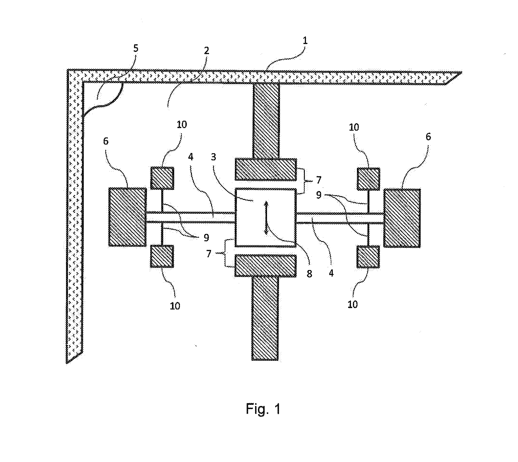
[0020]With reference to FIG. 1, the pressure sensor in the invention comprises a box 1, substantially in the form of a rectangular parallelepiped in this example, defining a housing 2 under a secondary vacuum (in this embodiment, the pressure is no greater than 10−5 atmospheres).
[0021]A resonator 3 in the form of a single flyweight is received in the housing 2 and is suspended by flexible beams given overall reference 4 from an elastically deformable diaphragm 5 that closes the housing 2 (the diaphragm 5 closes the top opening of the housing 2 and lies in a plane parallel to the sheet of FIG. 1).
[0022]The resonator 3 is substantially in the form of a rectangular block, as shown in FIG. 1. The length of the seismic size of the resonator 3 lies substantially in the range 20% to 40% of the total length of the resonator 3, and is preferably 25%. The resonator 3 is not in direct contact with the diaphragm 5.
[0023]The beams 4 form two suspension arms for the resonator 3 that are positione...
second embodiment
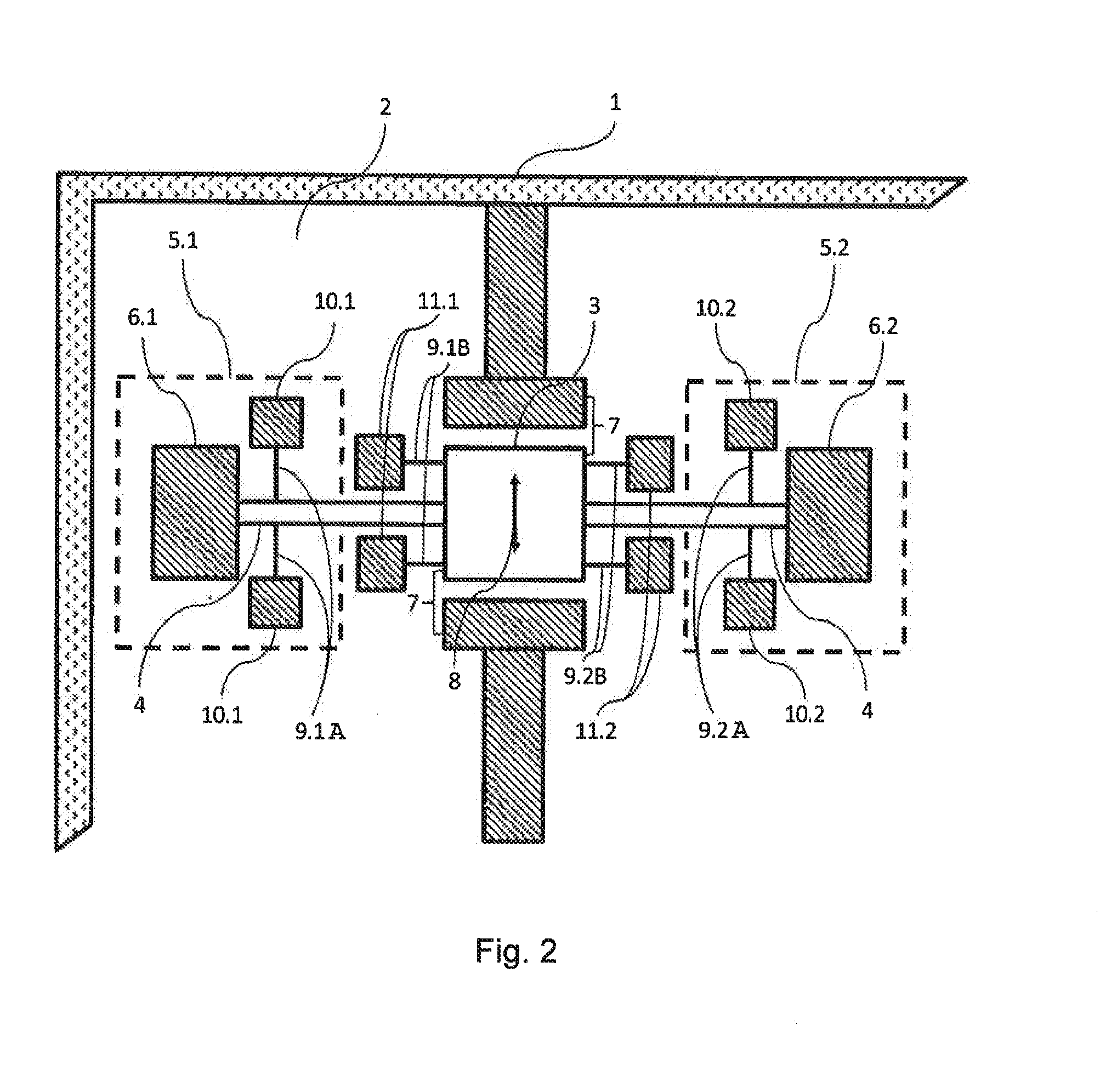
[0035]With reference to FIG. 2, which shows the second embodiment, the box 1 is in the form of a frame on which there extend both a diaphragm 5.1 and a diaphragm 5.2, which diaphragms are coplanar.
[0036]This defines a cavity in which there is located a resonator 3 that is suspended from the diaphragm 5.1 and from the diaphragm 5.2 by beams 4. Two beams 4 have one end secured to the resonator 3 and an opposite end secured to a respective stud 6.1, 6.2.
[0037]The sensor has first strain gauges 9.1A, 9.2A that are identical to the strain gauges 9 of the first embodiment, each having one end secured to a stud 10.1, 10.2 secured to the respective diaphragm 5.1, 5.2 and an opposite end secured to one of the beams 4 in such a manner that the first strain gauges 9.1A, 9.2A perpendicular to the beams 4 and parallel to the diaphragms 5.1, 5.2 form differential pairs. One of the strain gauges 9.1A is in tension while the other strain gauge 9.1A is in compression, and vice versa. The same applie...
third embodiment
[0042]With reference to FIG. 3, and in the third embodiment, the box 1 is in the form of a rectangular parallelepiped with four lateral openings giving access to the housing 2 (one opening in each of the sides of the box 1). These openings are closed by diaphragms so as to form a first pair of diaphragms 50.1 and a second pair of diaphragms 50.2, each pair of diaphragms closing the openings of two opposite sides of the box 1 and thus forming a cavity that is subjected to a secondary vacuum. The box 1 is arranged in such a manner that the first pair of diaphragms 50.1 and the second pair of diaphragms 50.2 are subjected to different pressures (differential pressure measurement). For this purpose, the box 1 has at least a first opening (not shown) giving access to the diaphragms 50.1 of the first pair of diaphragms 50.1, and at least one second opening (not shown) giving access to the diaphragms 50.2 of the second pair of diaphragms 50.2, said openings leading for example to opposite ...
PUM
| Property | Measurement | Unit |
|---|---|---|
| length | aaaaa | aaaaa |
| length | aaaaa | aaaaa |
| length | aaaaa | aaaaa |
Abstract
Description
Claims
Application Information
 - R&D
- Intellectual Property
- Life Sciences
- Materials
- Tech Scout
- Unparalleled Data Quality
- Higher Quality Content
- 60% Fewer Hallucinations
Browse by: Latest US Patents, China's latest patents, Technical Efficacy Thesaurus, Application Domain, Technology Topic, Popular Technical Reports.
© 2025 PatSnap. All rights reserved.Legal|Privacy policy|Modern Slavery Act Transparency Statement|Sitemap|About US| Contact US: help@patsnap.com


