
Correcting an error in a memory device

a memory device and error correction technology, applied in the field of computing architectures, can solve the problems of further reducing the verification process of a decoder by ecc signatures, and achieve the effect of optimizing performance and endurance and less latency

Inactive Publication Date: 2017-01-05
IBM CORP
View PDF2 Cites 19 Cited by
  • Summary
  • Abstract
  • Description
  • Claims
  • Application Information

AI Technical Summary

Benefits of technology

This patent text explains how to improve the performance and endurance of SSDs by balancing the correction capability with the thermal profile. By using less bits to store ECC program code in low temperature regions, the storage space can be preserved. A smaller ECC signature also reduces the verification processes of the decoder. This results in less latency. The ECC capability can be set based on the temperature boundary and specification, rather than always aiming for the worst case scenario. In summary, this patent explains how to optimize the performance of SSDs by optimizing ECC capability and thermal management.

Problems solved by technology

A smaller ECC signature further reduces the verification processes of a decoder that validates the integrity of the data.

Method used


Image

  • Correcting an error in a memory device
  • Correcting an error in a memory device
  • Correcting an error in a memory device

Examples


Embodiment Construction

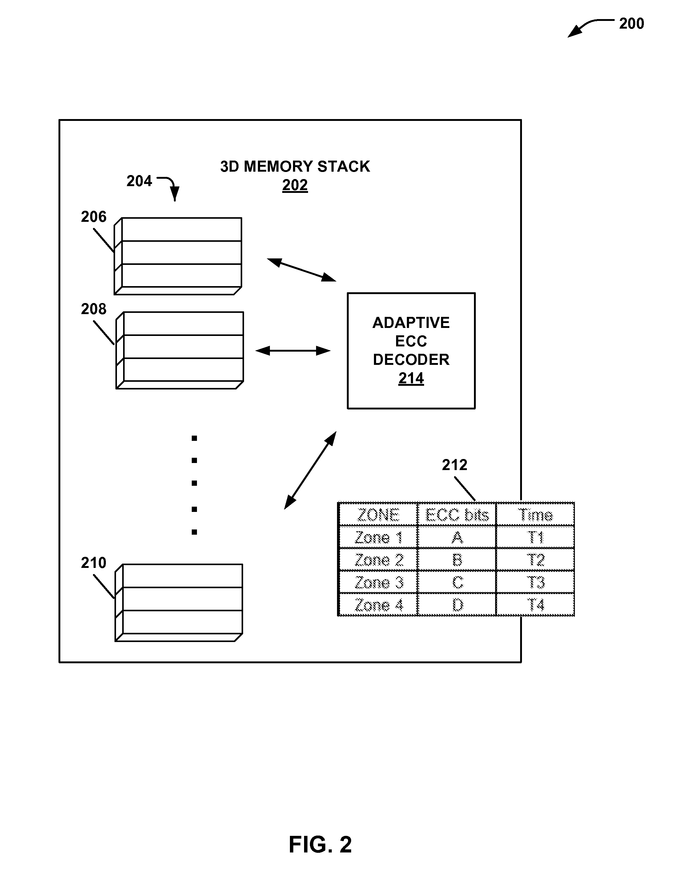
[0016]An embodiment of a system and an associated method provides error correction that accounts for temperature gradients between flash memory devices. The system may use relatively stronger error correction (e.g. more error correction bits) for flash memory devices that are in relatively hotter zones than with devices located in relatively cooler zones. An ECC infrastructure may be optimized in response to temperature operating conditions in a manner that does not substantially affect Reliability, Availability, and Serviceability (RAS) performance.

[0017]A group of memory devices in a three-dimensional (3D) integrated circuit, or 3D stack, may be grouped into zones based on thermal profiles. Different ECC level decoders may be used for each zone. Each zone may be grouped in such a manner as there is a significant temperature gradient between any two zones. ECC correction capability may be applied for any particular zone as a function of operational temperature range.

[0018]According...


PUM


Abstract

In an example, a method of correcting an error in a memory device includes determining a temperature profile associated with a region of a memory device. The temperature profile is one of a plurality of temperature profiles each associated with a respective region of a plurality of regions of the memory device. The method includes determining a correction capability based on the thermal profile. The method also includes correcting an error in the memory region using the determined correction capability.

Description

I. CROSS REFERENCE TO RELATED APPLICATIONS[0001]This application is a continuation application and claims priority from U.S. patent application Ser. No. 14 / 789,055, entitled “ERROR CORRECTION BASED ON THERMAL INTERFACE PROFILE OF FLASH MEMORY DEVICE,” filed on Jul. 1, 2015, which is incorporated herein in its entirety.II. FIELD OF THE DISCLOSURE[0002]The present disclosure relates generally to computing architectures, and in particular, to a system and a method of managing error corrections in memory.III. BACKGROUND[0003]Elevated and non-uniform temperatures can negatively impact the reliability of flash memory devices, such as multi-level cell (MLC) NAND and solid state drive (SSD) products. Such reliability impacts become more pervasive as the sizes of flash memory devices are scaled down. In one example, a gradient temperature difference may be present between a top die and a bottom die of a memory stack. In another example, a temperature may be disproportionately higher within a...

Claims


Application Information

Patent Timeline
Patent Type & Authority Applications(United States)
IPC IPC(8): G06F11/10H03M13/35G11C29/52
CPCG06F11/1048G11C7/04G11C2029/0409G11C2029/0411G11C29/52G06F3/0619G06F3/064G06F3/0653G06F3/0679G06F11/1072H03M13/356
Inventor CHINNAKKONDA VIDYAPOORNACHARY, DIYANESH B.MATHIYALAGAN, VIJAY ANANDTRESSLER, GARY A.
Owner IBM CORP
Learn More