
Adaptive plasma cutting system and method

a plasma cutting and adaptive technology, applied in plasma welding apparatus, plasma technique, manufacturing tools, etc., can solve problems such as component wear, component wear, component wear, and anomalies, and system does not optimize the cutting process

Active Publication Date: 2017-01-05
LINCOLN GLOBAL INC
View PDF4 Cites 38 Cited by
  • Summary
  • Abstract
  • Description
  • Claims
  • Application Information

AI Technical Summary

Benefits of technology

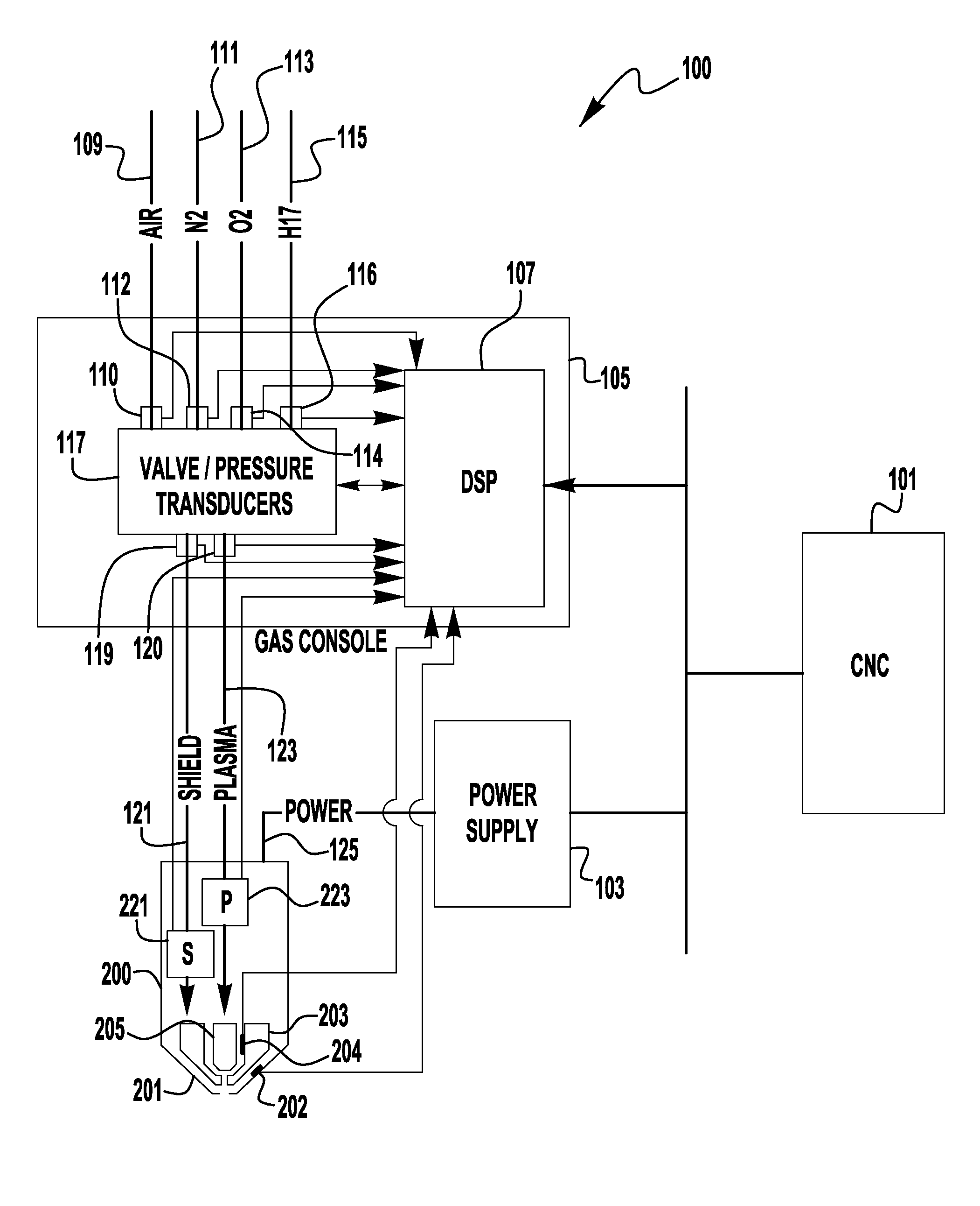
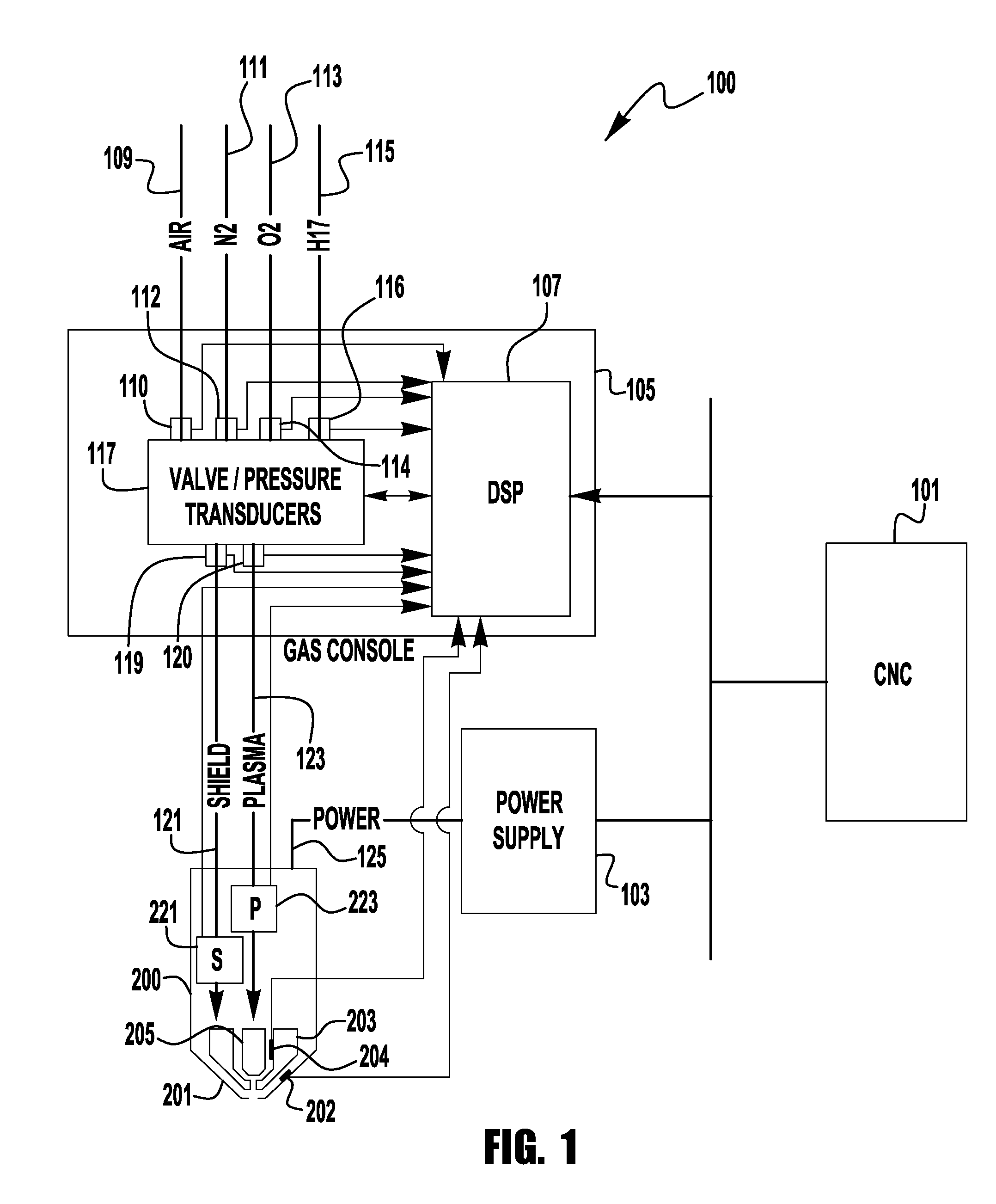
The present invention is related to equipment and methods for plasma cutting torches that use dynamic pressure sensing to control the cutting process. This allows for real-time adjustments to be made to the cutting operation, improving efficiency and accuracy. The invention involves utilizing pressure sensors placed throughout the system and the torch to collect data, which is then used to adjust the cutting process in response. This results in faster cutting times and better quality work.

Problems solved by technology

These systems represent a compromise on gas flow control and do not optimize the cutting process.
Further, such a system does not account for system to system variations, leaks, component wear, valving changes and anomalies, etc.

Method used


Image

  • Adaptive plasma cutting system and method
  • Adaptive plasma cutting system and method
  • Adaptive plasma cutting system and method

Examples


Embodiment Construction

[0019]Exemplary embodiments of the invention will now be described below by reference to the attached Figures. The described exemplary embodiments are intended to assist the understanding of the invention, and are not intended to limit the scope of the invention in any way. Like reference numerals refer to like elements throughout.

[0020]It is noted that for purposes of the following discussion, the system will be discussed as a liquid cooled, mechanized plasma arc cutting system. However, exemplary embodiments are not limited to being used in such arc cutting systems, and embodiments can be used in hand held cutting systems as well as air cooled systems. Thus, the following discussions are intended to be exemplary and informative. Further, discussions below will use terminology such as “distal” and “downstream”. In the context of this application it is understood that these terms mean closer to the end of the torch from which the plasma is emitted. For example, the distal end of the...


PUM

PropertyMeasurementUnit
pressureaaaaaaaaaa
pressureaaaaaaaaaa
gas pressureaaaaaaaaaa

Abstract

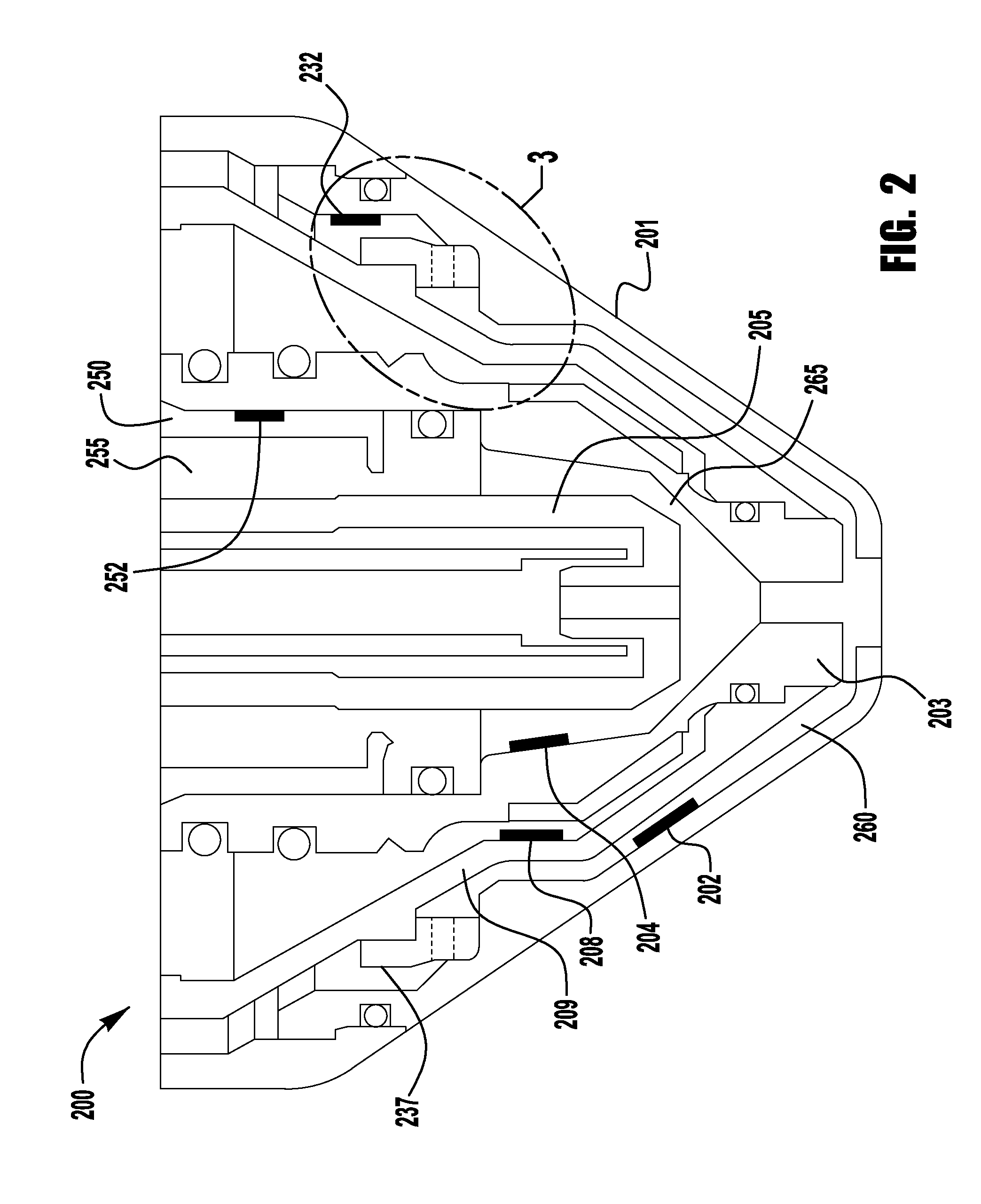
A plasma torch system and method is provided, in which the system utilizes a number of pressure sensors throughout the system and the torch to detect the flow / pressure of shield and plasma gas during operation. The detected pressures are used by the system to dynamically control the system pressures to optimize the cutting operation.

Description

BACKGROUND OF THE INVENTION[0001]Field of the Invention[0002]Systems and methods of the present invention relate to plasma cutting, and more specifically to arc plasma cutting using an adaptive control system which detects and utilizes system pressures to optimize performance.[0003]Description of the Related Art[0004]The use of plasma cutting systems in various industries has grown, and as a result there is an increasing need to increase the durability and longevity of torches and their components. This is particularly true with regarding to some internal torch parts, such as the nozzle and electrode, and some external torch parts, such as the shield cap. As is generally known, plasma cutting involves the use of high current plasma jet which generates a large amount of heat during cutting and can generate spatter during piercing or arc starting. Additionally, plasma cutting utilizes gases for the cutting operation, such as shielding gases and plasma gases. These gases aid in stabili...

Claims


Application Information

Patent Timeline
Patent Type & Authority Applications(United States)
IPC IPC(8): B23K10/00H05H1/26H05H1/34
CPCB23K10/006B23K10/00H05H1/26H05H1/34H05H1/3405H05H1/3494
Inventor WINN, JACKIE L.
Owner LINCOLN GLOBAL INC
Learn More