Eureka AIR delivers breakthrough ideas for toughest innovation challenges, trusted by R&D personnel around the world.

Automated Resin Ridge Reduction System

a resin ridge and automatic technology, applied in the field of composite structures, can solve the problems of unfavorable aircraft manufacturing, unfavorable aircraft manufacturing, and ridges along the edges of caul plates, and achieve the effects of reducing inconsistency, reducing inconsistency, and reducing inconsistency

Active Publication Date: 2016-12-29
THE BOEING CO
View PDF41 Cites 44 Cited by
  • Summary
  • Abstract
  • Description
  • Claims
  • Application Information

AI Technical Summary

Benefits of technology

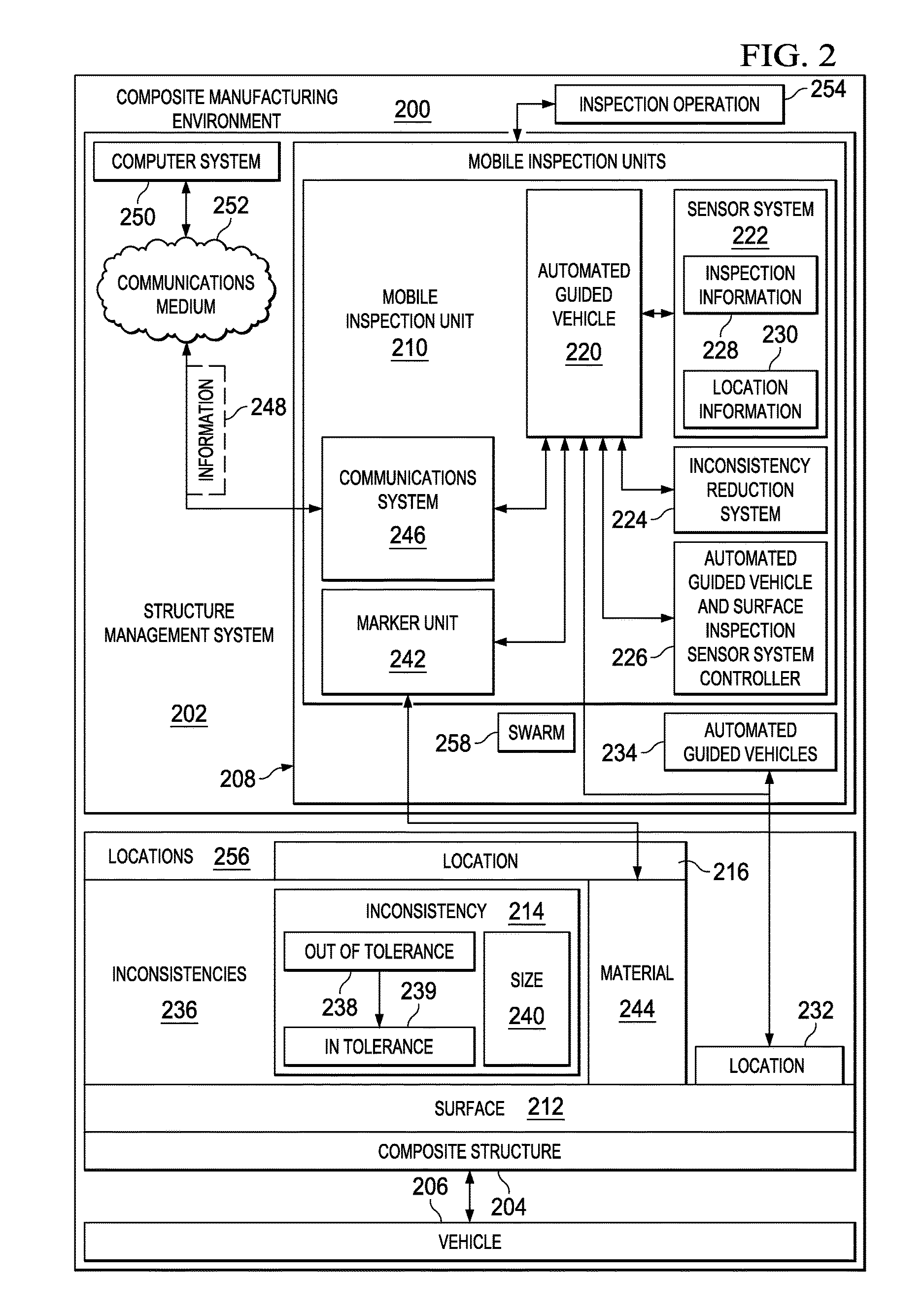
The present patent provides a method for reducing inconsistencies on the surface of a composite structure using an automated guided vehicle and a surface inspection sensor system. The sensor system automatically generates inspection information about the surface of the composite structure and identifies any inconsistencies that may be out of tolerance. The vehicle autonomously controls its movement on the surface and identifies the location of the inconsistency. The controller then tags the location of the inconsistency so that it can be efficiently reduced, such as by physically marking it with a material or storing the coordinates of the location. Overall, this method allows for quick and accurate detection and reduction of inconsistencies on the surface of a composite structure.

Problems solved by technology

These caul plates, however, may cause ridges to form along the edges of the caul plates.
Other operations that may cause undesired resin ridges include bagging creases and transition areas between co-bonded and co-cured parts.
Further, reworking or discarding composite structures may increase the cost in manufacturing aircraft by an undesirable amount.

Method used


Image

  • Automated Resin Ridge Reduction System
  • Automated Resin Ridge Reduction System
  • Automated Resin Ridge Reduction System

Examples


Embodiment Construction

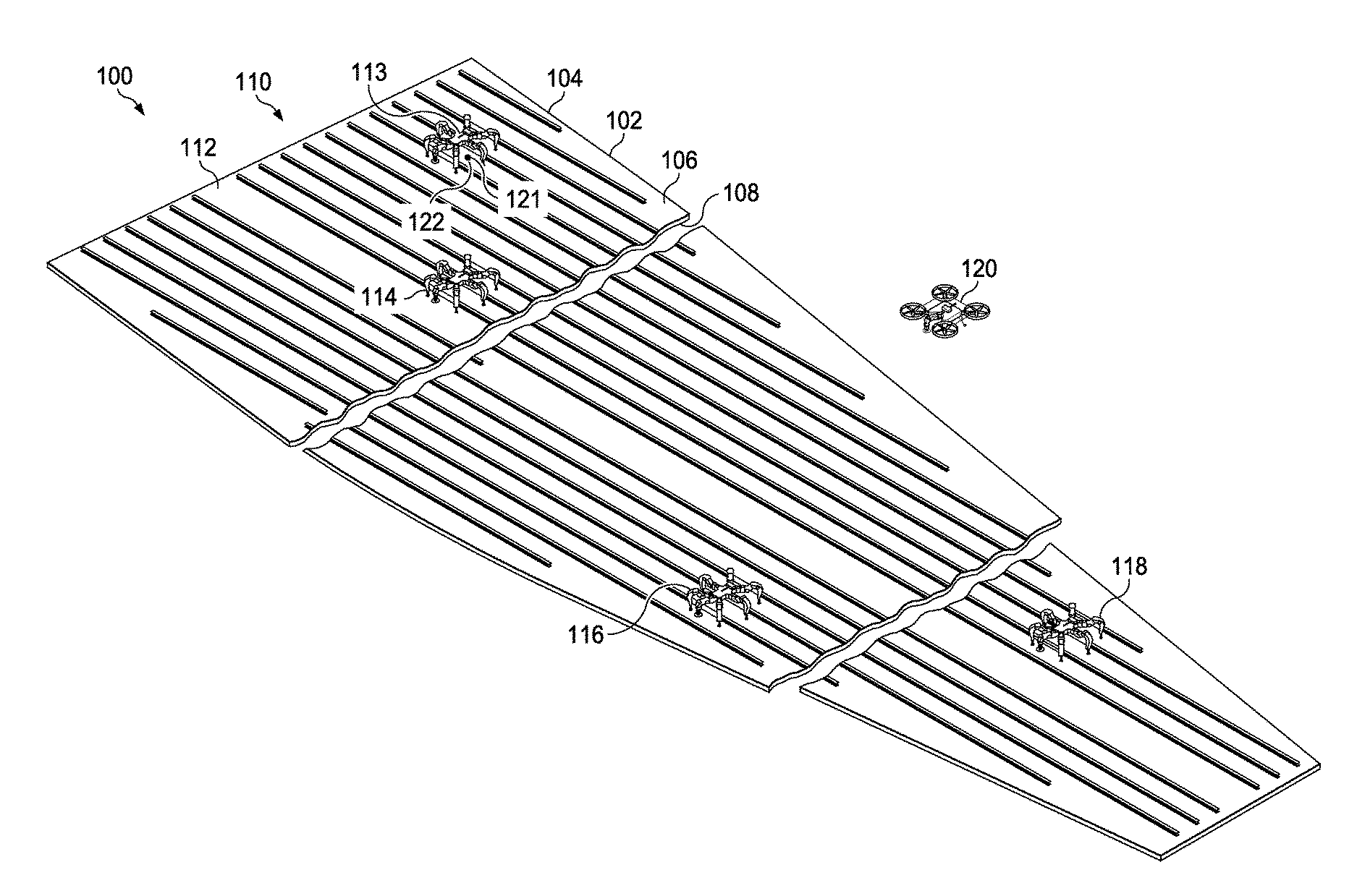
[0031]The illustrative embodiments recognize and take into account one or more different considerations. For example, without limitation, the illustrative embodiments recognize and take into account that in manufacturing composite wings for aircraft, caul plates used to reduce the effects of crenulations from laying up tape and fabric and smooth out transition areas may result in ridges formed of resin. The illustrative embodiments recognize and take into account these types of ridges may be reduced in size through operations such as sanding the resin ridges.

[0032]Currently, with the concern of sanding into fibers, human operators may inspect the wing for defects and perform sanding by hand. In some cases, the human operators may use a sanding tool such as a pneumatic tool with a rotary grinding attachment. This type of process for removing excess resin may be very labor-intensive. Additionally, the illustrative embodiments recognize and take into account that in reducing resin, san...


PUM


Abstract

An apparatus comprises an automated guided vehicle that moves on a surface of a composite structure during operation of the apparatus to inspect the composite structure, a surface inspection sensor system associated with the automated guided vehicle, and an automated guided vehicle and surface inspection sensor system controller in communication with the automated guided vehicle and the surface inspection sensor system.

Description

BACKGROUND INFORMATION[0001]1. Field[0002]The present disclosure relates generally to composite structures and, in particular, to composite structures for vehicles. Still more particularly, the present disclosure relates to a method and apparatus of inspecting and reducing resin ridges on composite structures for aircraft.[0003]2. Background[0004]In manufacturing composite wings for aircraft, caul plates may be used to reduce the effects of crenulations from laying up tape and fabric. Caul plates may also be used to smooth out transition areas.[0005]These caul plates, however, may cause ridges to form along the edges of the caul plates. Inspections may be performed to identify ridges that may have a size that is greater than desired. Other operations that may cause undesired resin ridges include bagging creases and transition areas between co-bonded and co-cured parts. Further, reworking or discarding composite structures may increase the cost in manufacturing aircraft by an undesir...

Claims


Application Information

Patent Timeline
Patent Type & Authority Applications(United States)
IPC IPC(8): G01B11/30G05D1/00G01M17/007
CPCG01B11/303G05D1/0088G01M17/007G01N21/9515G01N2021/8472G01N2021/9518G01B11/24B64F5/60B64U2101/26B64U60/50B64U10/14B64U30/26B64U2101/30
Inventor CLARK, GREGORY L.
Owner THE BOEING CO
Why Eureka
Eureka Blog
Learn More