
Aircraft

a technology for aircraft and propellers, applied in the field of short takeoff and landing aircraft, can solve the problems of low propulsion efficiency of turbofans in time of cruise, and few of them succeeded in practical use, and achieves moderate high gliding efficiency, high efficiency, and high propulsion efficiency

Inactive Publication Date: 2016-12-29
FELDMAN YURI
View PDF18 Cites 50 Cited by
  • Summary
  • Abstract
  • Description
  • Claims
  • Application Information

AI Technical Summary

Benefits of technology

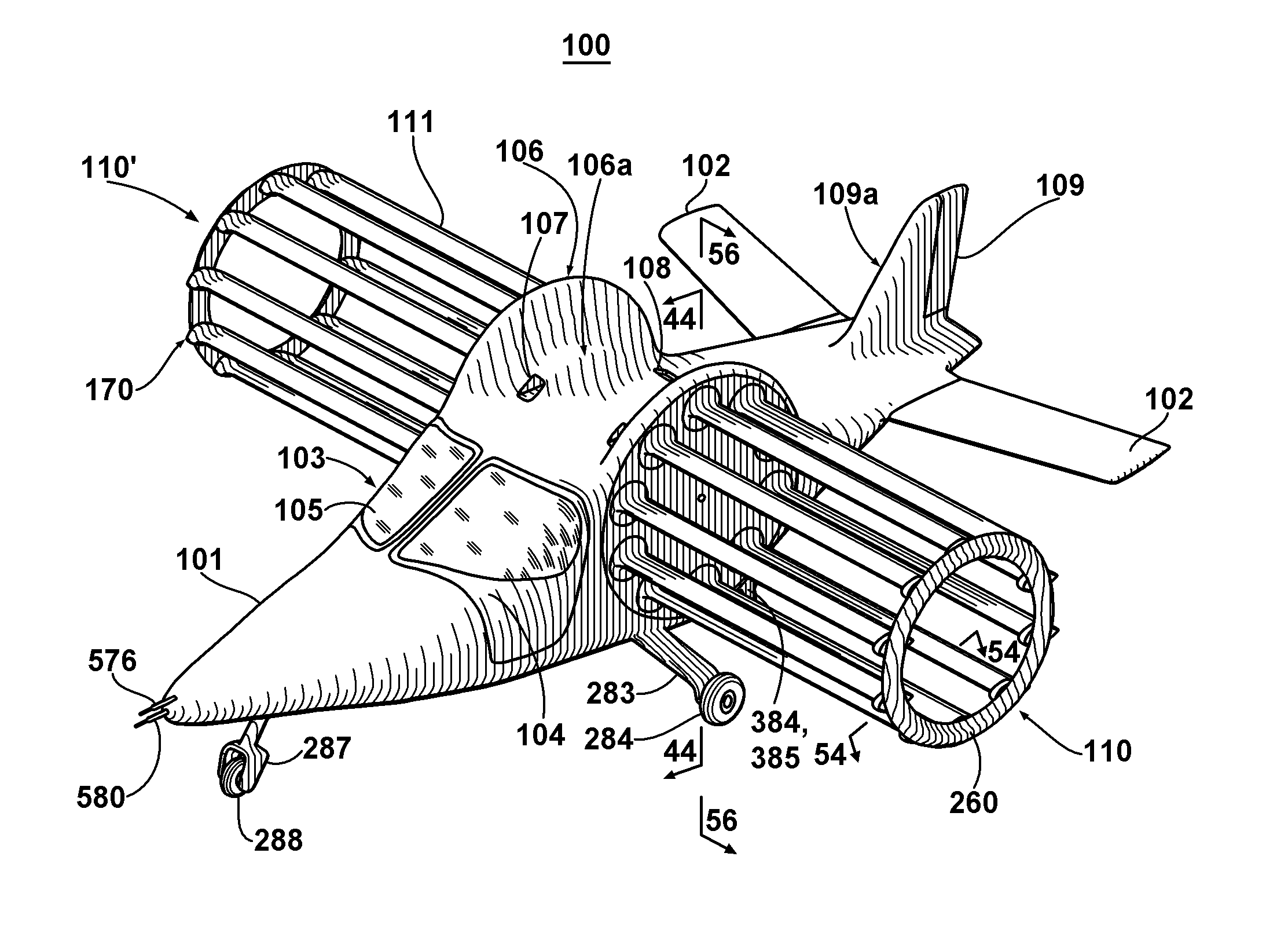
The present invention is an aircraft that has high propulsion efficiency, can glide at a moderate speed, and can perform short takeoff and landing (STOL) while maintaining a subsonic cruise speed. It also uses high torque electrical engines for power flight and has the ability to recover energy during descent, deceleration, or both. The aircraft has a simple set-up for the engines and rotors, and has accumulators placed along the sides of the fuselage to compensate for load variations and keep the fuselage relatively free. Additionally, a combustion engine can be coupled with a generator to utilize warm cooling air from the rotor's engines for combustion fuel with additional intake and exhaust along the trailing edge of the fuselage.

Problems solved by technology

Progress in having high performance airplane still is today neediness, but the progress saturated after long way of airplanes optimization.
Nevertheless, propulsion efficiency of turbofan in time of cruise is only about 50 percents, since its fan stage only particularly participates in overall propulsion.
Other kinds of aircrafts were considered also, but only few of them succeeded in practical use.
One of them is helicopter, which propulsion efficiency in time of cruise more than 90 percents, but its lift to drag ratio is too low for having concurrency with airplane.
They have big advantage in performance, permitting have propulsion efficiency more than 95 percents and high lift to drag ratio, but they have big drawback: oscillation from flapping wings inevitable propagated to fuselage, so flight cannot be comfortable for humans.
They were under development long time from beginning of twenty century, but still not succeeded for human flight.
Currently they used only for low scale models, without great advantage over low scale helicopter models.
Non-succeeding of cyclorotors for aircraft was mainly caused by wrong understand of their abilities upon transmitting elements of theory and practice from development of airplanes and helicopters to their development.
Cyclorotors can also operate for this particular case, but they cannot leverage they potential by this way.

Method used


Image

  • Aircraft
  • Aircraft
  • Aircraft

Examples


Embodiment Construction

[0140]Prior to describing details of preferred embodiment, a discussion is provided of related matter for having correct attitude of understanding functionality of some kind of aircrafts, to which the preferred embodiment belongs.

[0141]Corner aspects of the invention were originated from following thought experiment, which I imagined in one day.

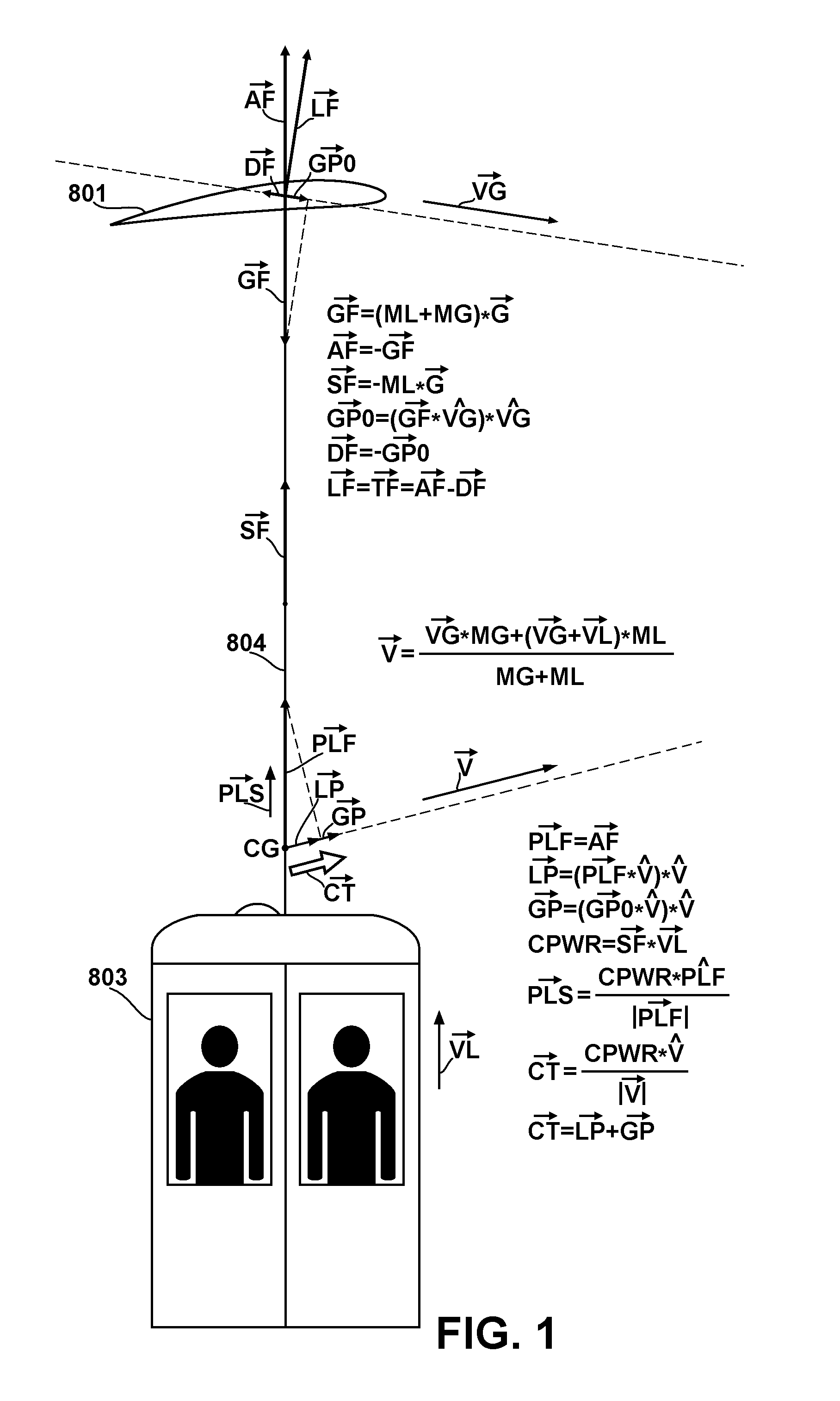
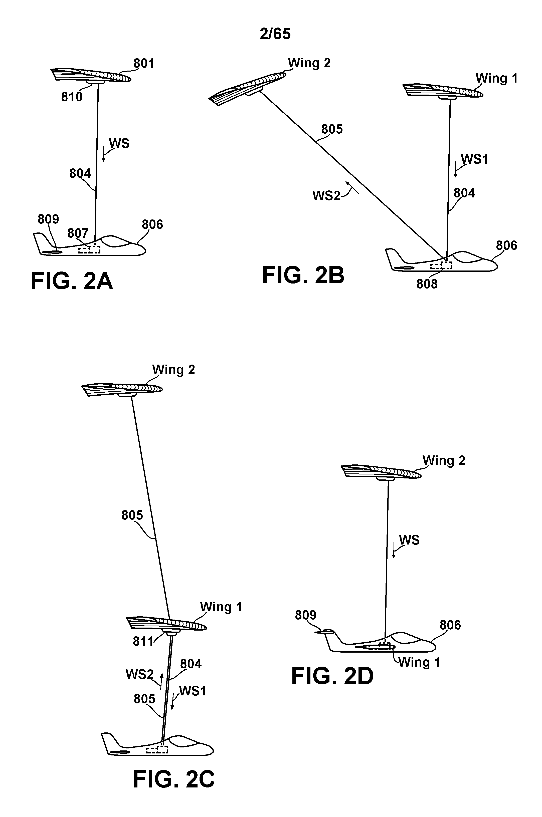
[0142]Consider an elevator (or lift), which going up on some wire, which winding in elevator's own drum by power of its own engine. And now consider also: other end of the wire is fixedly connected to some wing or lightweight glider, which is gliding down. Also consider horizontal components of speed of both: elevator and glider are equal, and also the movement of both is without of acceleration. Additionally consider: let aerodynamic drags of the elevator and of the wire itself are negligible. So this system will be in the presented movement until exists free length of the wire. But let stay away now from the problem of limited time of the m...


PUM


Abstract

Conception introduced for performing powered flight of aircraft by performing work against gravity force, using gliding wing as steady support, namely “flying elevator” conception, and aircraft developed, based on cyclorotor scheme with elaborated steering solution, continuing in flexible handling and control. Said aircraft correctly and optimally implements said conception after presented detailed modeling, simulation and analyzing, having ability for flight with exceptionally high propulsion efficiency, moderate lift to drag ratio and short takeoff and landing. Additionally, it has ability for recuperative descent and deceleration, utilizing direct driving from high torque electrical engines, which can optionally hybridized with combustion engine, and covers speed range up to limits of subsonic flight.

Description

FIELD OF THE INVENTION[0001]The presented invention generally relates to short takeoff and landing aircraft. In particular the present invention relates to such aircraft, which used pair of rotors from parallel oriented rotated wings for obtain overall aerodynamic force with desired components in vertical and horizontal directions enough to accomplish entire flight, in place of pair of stationary wings and separate propulsors. The invention also relates to steering those wings on rotors and handling entire aircraft.BACKGROUND OF THE INVENTION[0002]Contemporary aviation has in its history remarkable time when first aircraft for powered flight was invented. Looking only from point of view of powering, this invention can be considered as application of rotated wings actuator, known as propeller, to non-powered glider. Prior this time propeller was well known for using for marine applications and its successful adaptation to air applications opened the airplane era and defined a general...

Claims


Application Information

Patent Timeline
Patent Type & Authority Applications(United States)
IPC IPC(8): B64C39/00B64C29/00B64C13/08B64C13/14G06F17/10B64D43/00G05D1/10G01P13/02G06F17/50B64C27/32B64C13/34
CPCB64C39/005B64C27/32B64C29/0008B64C13/08B64C13/14G06F17/10B64D43/00G05D1/102G01P13/025G06F17/5009B64C13/34B64C31/02B64C31/028B64D33/08B64C13/44G06F30/20Y02T50/50
Inventor FELDMAN, YURI
Owner FELDMAN YURI
Learn More