
Mobile fracturing pump transport for hydraulic fracturing of subsurface geological formations

a technology of hydraulic fracturing and pump transport, which is applied in the direction of piston pumps, positive displacement liquid engines, borehole/well accessories, etc., can solve the problems of complex planning for fracturing operations, large-scale fracturing operations at well sites, and large investment in equipment, labor and fuel

Active Publication Date: 2016-12-22
TYPHON TECH SOLUTIONS (U S) LLC
View PDF4 Cites 247 Cited by
  • Summary
  • Abstract
  • Description
  • Claims
  • Application Information

AI Technical Summary

Benefits of technology

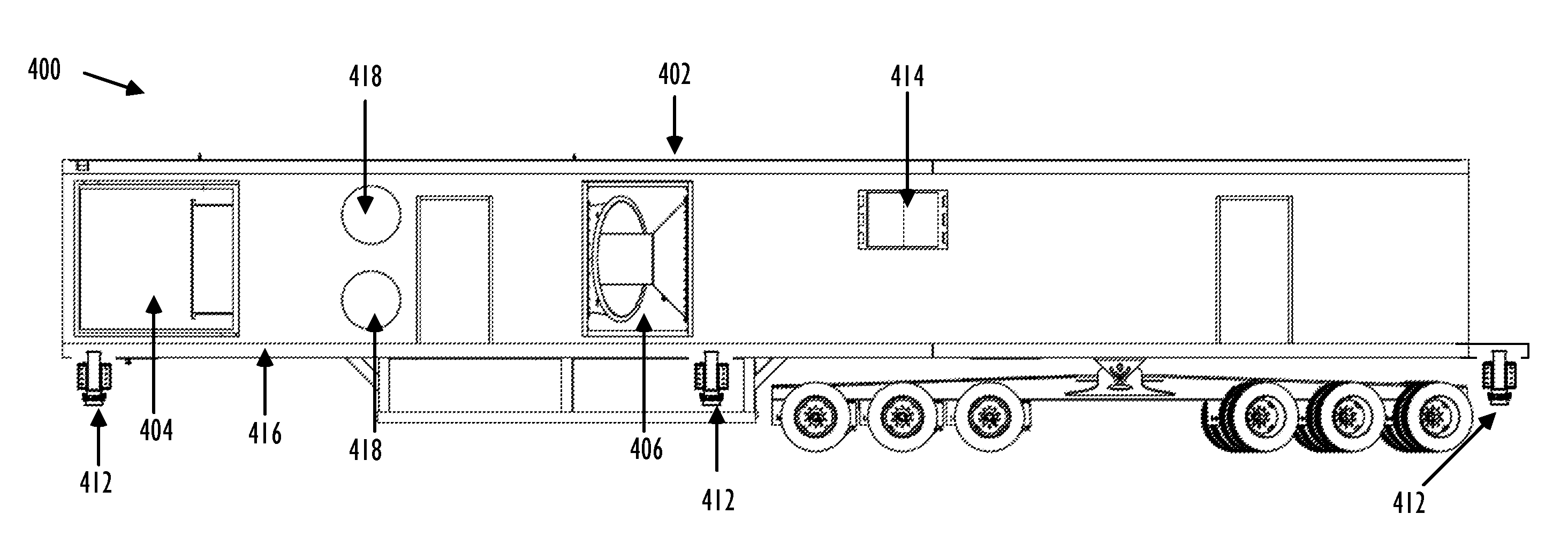
This patent describes a system and method for pumping and pressurizing fracturing fluid. The system includes a mobile transport, an electric prime mover, and a drive line assembly with an engagement panel that allows for selective engagement and disengagement of fracturing pumps. The method involves receiving a remote command to engage or disengage the fracturing pumps and driving one of the pumps while disengaging the other using the drive line assembly. The technical effects of this patent include improved efficiency and flexibility in fracturing fluid pumping and pressurizing, as well as reduced emissions and noise from the pumps.

Problems solved by technology

Implementing large-scale fracturing operations at well sites typically requires extensive investment in equipment, labor, and fuel.
For instance, a typical fracturing operation uses a variety of fracturing equipment, numerous personnel to operate and maintain the fracturing equipment, relatively large amounts of fuel to power the fracturing operations, and relatively large volumes of fracturing fluids.
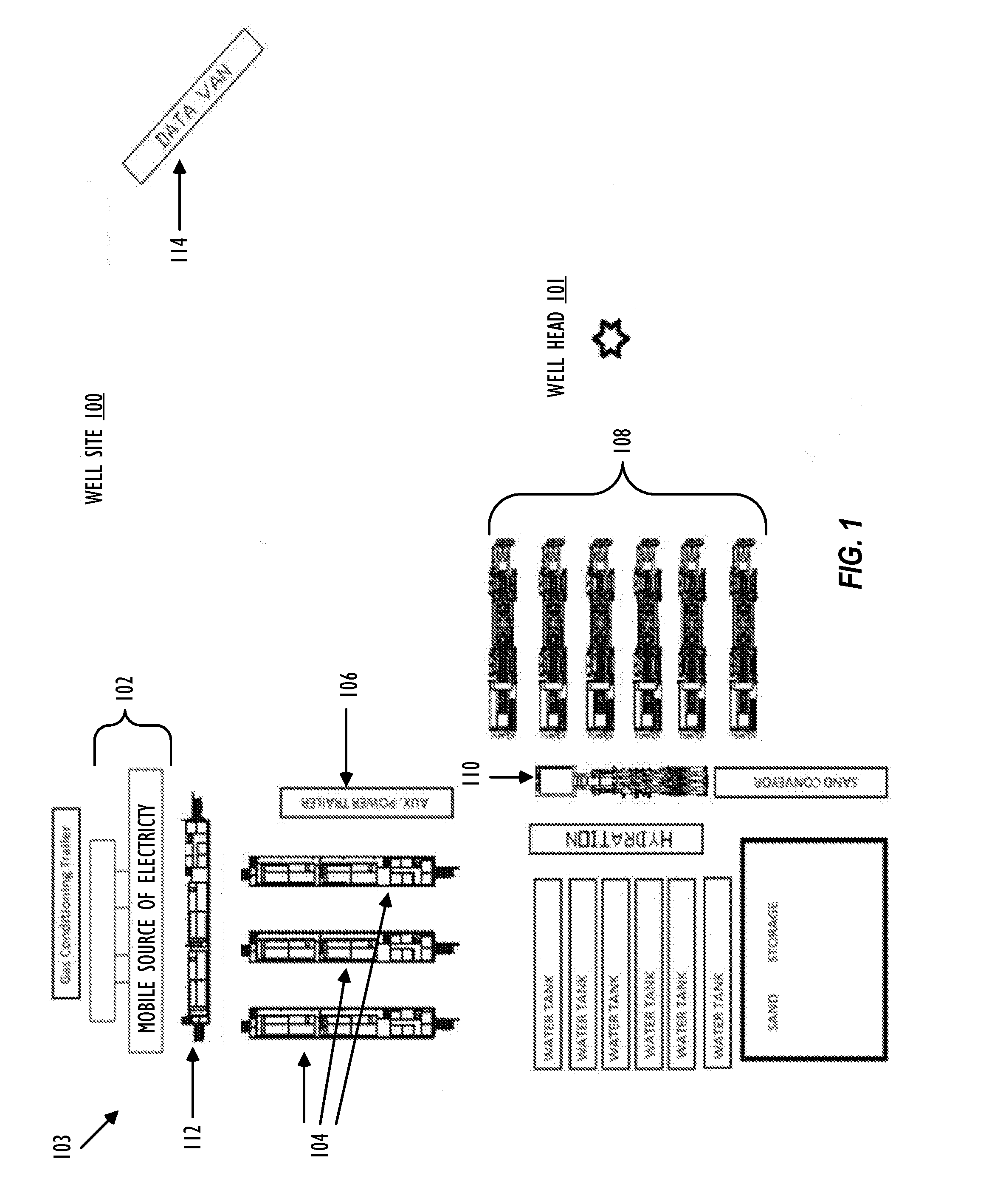
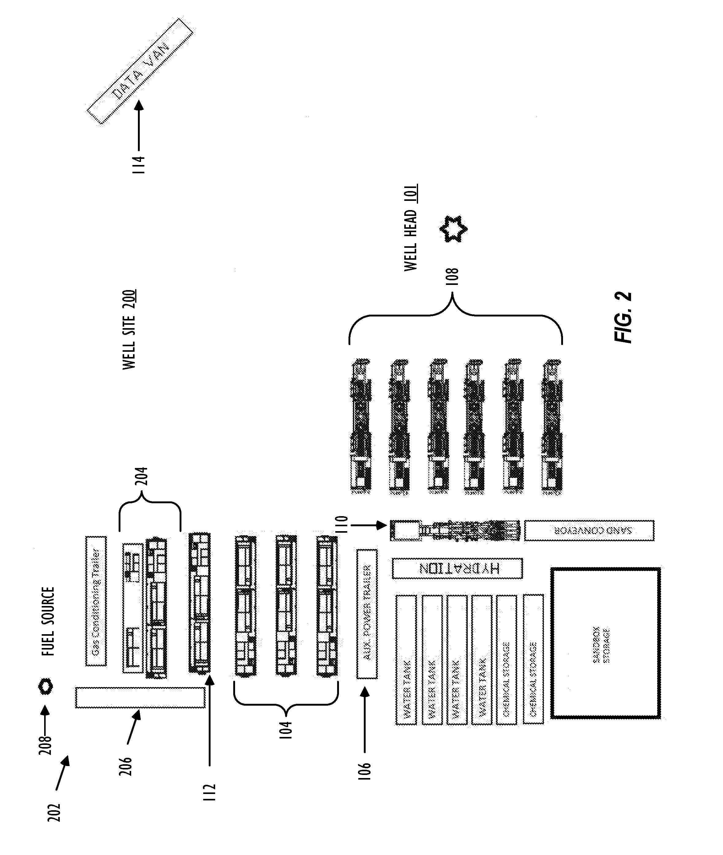
As such, planning for fracturing operations is often complex and encompasses a variety of logistical challenges that include minimizing the on-site area or “footprint” of the fracturing operations, providing adequate power and / or fuel to continuously power the fracturing operations, increasing the efficiency of the hydraulic fracturing equipment, and reducing any environmental impact resulting from fracturing operations.

Method used


Image

  • Mobile fracturing pump transport for hydraulic fracturing of subsurface geological formations
  • Mobile fracturing pump transport for hydraulic fracturing of subsurface geological formations
  • Mobile fracturing pump transport for hydraulic fracturing of subsurface geological formations

Examples


Embodiment Construction

[0033]As used herein, the term “transport” refers to any transportation assembly, including, but not limited to, a trailer, truck, skid, and / or barge used to transport relatively heavy structures, such as fracturing equipment.

[0034]As used herein, the term “trailer” refers to a transportation assembly used to transport relatively heavy structures, such as fracturing equipment that can be attached and / or detached from a transportation vehicle used to pull or move the trailer. In one embodiment, the trailer may include the mounts and manifold systems to connect the trailer to other fracturing equipment within a fracturing system or fleet.

[0035]As used herein, the term “lay-down trailer” refers to a trailer that includes two sections with different vertical heights. One of the sections or the upper section is positioned at or above the trailer axles and another section or the lower section is positioned at or below the trailer axles. In one embodiment the main trailer beams of the lay-...


PUM


Abstract

Providing pressurized fracturing fluid with a fracturing pump transport comprising a first fracturing pump and a second fracturing pump that are coupled on opposite sides of a dual shaft electric motor. A first drive line assembly comprising a first engagement coupling that allows for selective engagement and / or disengagement of the first fracturing pump with the dual shaft electric motor. A second drive line assembly comprising a second engagement coupling that allows for selective engagement and / or disengagement of the second fracturing pump with the dual shaft electric motor. The fracturing pump transport also comprising an engagement panel that allows for selective engagement or disengagement at the first engagement coupling based on receiving a remote command.

Description

CROSS-REFERENCE TO RELATED APPLICATIONS[0001]This application is a continuation-in part of U.S. patent application Ser. No. 14 / 971,450, filed Dec. 16, 2015 by Jeffrey G. Morris et al. and entitled “Mobile Electric Power Generation for Hydraulic Fracturing of Subsurface Geological Formations, which claims the benefit of U.S. Provisional Patent Application No. 62 / 094,773, filed Dec. 19, 2014 by Jeffrey G. Morris et al. and entitled “Mobile Electric Power Generation and Electrically Powered Hydraulic Fracturing of Underground Formations,” all of which are hereby incorporated by reference as if reproduced in their entirety.BACKGROUND[0002]Hydraulic fracturing has been commonly used by the oil and gas industry to stimulate production of hydrocarbon wells, such as oil and / or gas wells. Hydraulic fracturing, sometimes called “fracing” or “fracking” is the process of injecting fracturing fluid, which is typically a mixture of water, sand, and chemicals, into the subsurface to fracture the s...

Claims


Application Information

Patent Timeline
Patent Type & Authority Applications(United States)
IPC IPC(8): E21B43/26F04B23/04F04B17/06F04B9/02F04B17/03
CPCE21B43/26F04B9/02F04B23/04F04B17/06F04B17/03F02C7/052F02C7/055F02C7/20F02C7/32E21B43/2607F16D2021/0653F16D48/062
Inventor MORRIS, JEFFREY G.JENSEN, NEALBODISHBAUGH, ADRIAN BENJAMIN
Owner TYPHON TECH SOLUTIONS (U S) LLC
Learn More