
Seamless tiled displays

Active Publication Date: 2016-12-15
BARCO NV +1
View PDF9 Cites 28 Cited by
  • Summary
  • Abstract
  • Description
  • Claims
  • Application Information

AI Technical Summary

Benefits of technology

The patent text describes a method for attaching display tiles to a support structure using a heat activated adhesive. The advantages of this method are that it reduces the risk of the tile moving and the seams between tiles being large. The thickness of the adhesive is controlled, which helps to control the dimensions of the gap between tiles and prevents the glue from seeping during manufacture or afterward. The glue is applied along the chamfered edges of the tile and the weight is applied perpendicularly along at least 2 edges, reducing the risk of damage to brittle substrates such as glass. Overall, this method reduces the risk of damage to the tiled display and the log team load on the connections.

Problems solved by technology

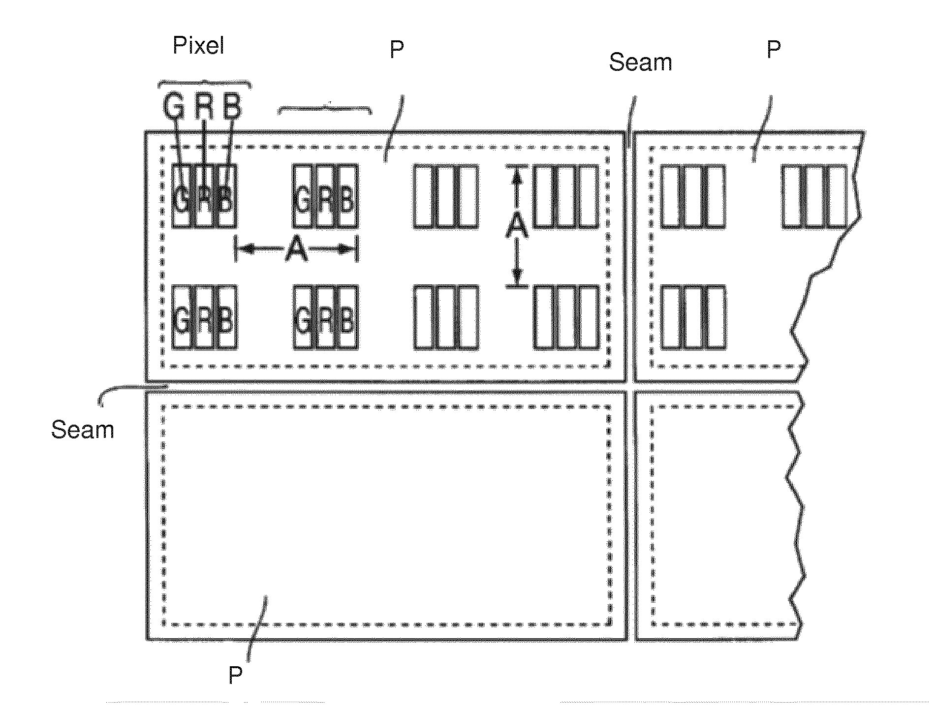
Nevertheless, the differential thermal expansion is still too large for seamless tiled displays where the width of the inter-tile seams must be equal or smaller than the distance between two adjacent pixels on the same tile.
But for tiled display with more than one row of adjacent screens, the tensioning mechanism cannot be hidden from the viewer.
The mechanism proposed in U.S. Pat. No. 5,185,677 thus does not allow the assembly of large, multi-rows seamless tiled displays.
However, the edges of a basic unit of this nature are fragile during transportation and the other drawbacks which are inherent to the assembly of basic units continue to exist.
a) The glue material itself is not very strong so it is not a good idea to have a large thickness of glue.
Step 1 can be messy during production and requires the surfaces to be cleaned and step 2 slows down production and hence increases production time and increases costs of production.
The pressure applied can break fragile substrates, e.g. made from glass.
Liquid glue is not compatible with the slanted / lateral gluing surfaces.
Such glue can forms stains and visible artefacts.
Also the installation effort is high, projectors must be readjusted if environmental conditions are changing and the wall size is practically limited

Method used


Image

  • Seamless tiled displays
  • Seamless tiled displays
  • Seamless tiled displays

Examples


Embodiment Construction

[0063]The present invention will be described with respect to particular embodiments and with reference to certain drawings but the invention is not limited thereto but only by the claims. The drawings described are only schematic and are non-limiting. In the drawings, the size of some of the elements may be exaggerated and not drawn on scale for illustrative purposes. Where the term “comprising” is used in the present description and claims, it does not exclude other elements or steps. Where an indefinite or definite article is used when referring to a singular noun e.g. “a” or “an”, “the”, this includes a plural of that noun unless something else is specifically stated. The term “comprising”, used in the claims, should not be interpreted as being restricted to the means listed thereafter; it does not exclude other elements or steps.

[0064]Furthermore, the terms first, second, third and the like in the description and in the claims, are used for distinguishing between similar elemen...


PUM


Abstract

A tile and tiled display system having at least two adjacent tiles each having a display screen with display pixels which are picture elements, whereby for coloured displays each pixel is comprised of a plurality light emitting or light modulating elements. Each of the tiles has at least one first substrate of a first material and at least one first layer of a second material fixed to the first substrate where the thickness of the at least one first layer is less than the thickness of the first substrate; the coefficient of thermal expansion of the first substrate is less than the coefficient of thermal expansion of the at least one first layer and the distance between the at least two tiles is less than the size of a pixel on the display screen. The first substrates of adjacent tiles can be brought in mechanical contact.

Description

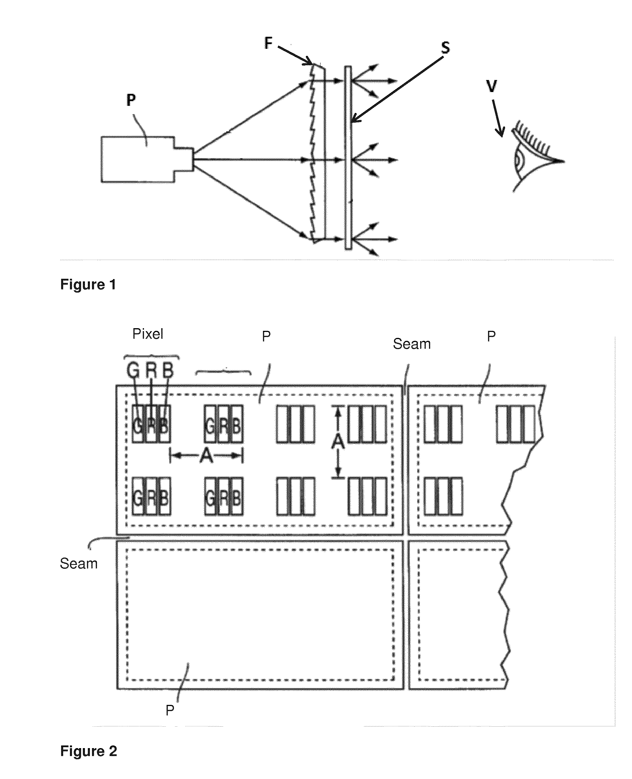
[0001]The present invention relates to tiled display, to display tiles and to methods of manufacturing and operating these including any software or controllers required to drive such displays.BACKGROUND[0002]FIG. 1 shows a diagrammatic representation of a rear projection set-up known from the prior art by means of a projector P, where a Fresnel lens F is disposed in front of the projection screen P. A brightness which is more regular for a viewer V from a particular angle of view can be brought about in this way.[0003]The projection screen P consists of a plastic material, for example polymethyl methacrylate (PMMA), associated with a diffuser. The diffuser is obtained e.g. by sand blasting the output surface (the surface seen by the viewer) of the projection screen or by mixing small particles (e.g. titanium dioxide) in a resin before polymerization.[0004]In tiled rear projection setup, several rear projection modules each with a screen P are disposed next to each other is a checke...

Claims


Application Information

Patent Timeline
IPC IPC(8): H04N9/31G03B21/62G02B3/08
CPCH04N9/3147G03B21/62G02B3/08H04N9/3141G03B21/10G03B21/56G09F9/35
Inventor HICKL, PETER
Owner BARCO NV
Learn More