Power supply device

a power supply device and voltage conversion technology, applied in the direction of electric variable regulation, process and machine control, instruments, etc., can solve problems such as potential instability of output voltag

Active Publication Date: 2016-12-08
ALPHA & OMEGA SEMICON CAYMAN
View PDF10 Cites 65 Cited by
  • Summary
  • Abstract
  • Description
  • Claims
  • Application Information

AI Technical Summary

Benefits of technology

[0023]FIG. 10 is waveforms showing that the master switch turn-on time determined by a later control signal is suppressed by a former control signal on the basis of FIG. 9.

Problems solved by technology

However, the load voltage, which varies with time, cannot be directly acquired from the load; the load voltage is instead sensed through the feedback network, which delays the load voltage measurement and thereby preventing synchronization of the driving component and the change state of the load voltage to switch the master switch in real time generating a difference between a present output voltage outputted to the load and a practical voltage requested by the load, and thus causing a potential instability for the output voltage.

Method used


Image

  • Power supply device
  • Power supply device
  • Power supply device

Examples


Embodiment Construction

[0028]With the combination of the embodiments, the technical scheme of the invention is clearly and completely illustrated, the described embodiments are only embodiments for describing the invention but not all embodiments, based on the embodiments, schemes obtained by technicians of the field without creative work all belong to the protection scope of the invention.

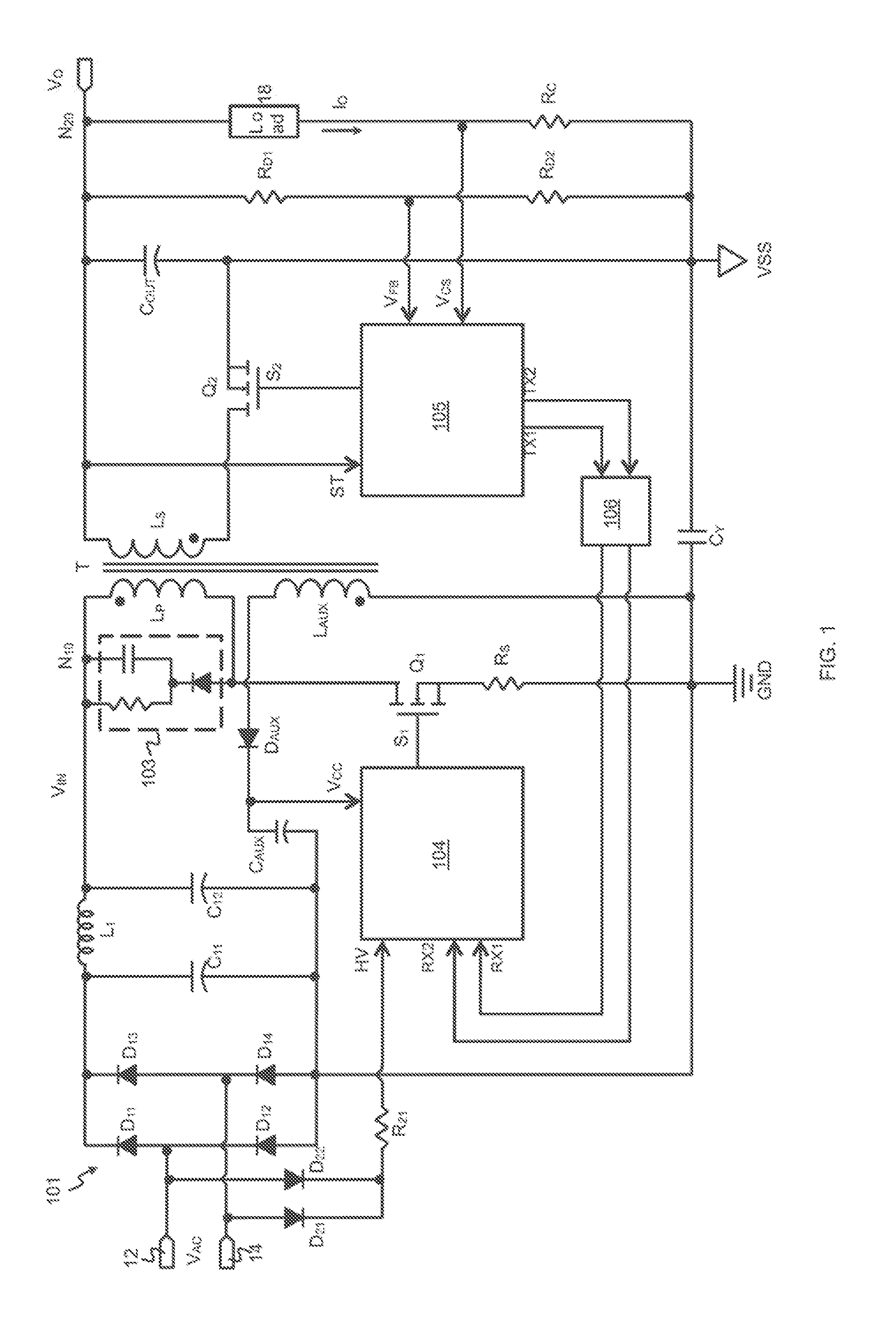
[0029]As shown in FIG. 1, a AC / DC FLYBACK voltage converter includes a power transformer T for voltage conversion mainly including primary windings LP and secondary windings LS, where the first end of the primary winding LP is used for receiving an input voltage VIN at an input node N10, and a master switch Q1 is connected between a second end of the primary winding LP and a ground terminal GND. The basic working mechanism is that the master switch Q1 is driven to be turned on and turned off through a primary winding controller, which is also known as a first controller 104, and when the master switch Q1 is turned on, t...


PUM


Abstract

The present invention relates to a power supply device for voltage converter, which includes a master switch, a first controller for generating a first pulse signal to drive the master switch to be turned on and turned off, a second controller for comparing a detection voltage representing an output voltage and/or load current with a first reference voltage to determine the logic state of a control signal generated by the second controller, and a coupling element connected between the first controller and the second controller for transmitting the logic state of the control signal to the first controller and enabling the first controller to determine the logic state of the first pulse signal according to the logic state of the control signal. The second controller includes a driving module for generating a second control signal to drive a synchronous switch to be turned on and turned off.

Description

CROSS-REFERENCE TO RELATED APPLICATIONS[0001]This application claims the priority benefit of Chinese patent application number 201510703725.1 filed Oct. 26, 2015 by a common inventor of this Application. The entire Disclosure made in the Chinese patent application number 201510703725.1 is hereby incorporated by reference.[0002]This application is a Continuation-In-Part (CIP) application of a pending U.S. patent application Ser. No. 14 / 562,727 filed on Dec. 7, 2014. The entire disclosure made in U.S. patent application Ser. No. 14 / 562,727 is hereby incorporated by reference.[0003]This application is a Continuation-In-Part (CIP) application of a pending U.S. patent application Ser. No. 14 / 562,729 filed on Dec. 7, 2014. The entire disclosure made in U.S. patent application Ser. No. 14 / 562,729 is hereby incorporated by reference.[0004]This application is a Continuation-In-Part (CIP) application of a pending U.S. patent application Ser. No. 14 / 562,731 filed on Dec. 7, 2014. The entire di...

Claims


Application Information

Patent Timeline
Patent Type & Authority Applications(United States)
IPC IPC(8): H02M3/335
CPCH02M3/33592H02M1/08H02M1/36H02M1/40H02M3/33523H02M1/0006Y02B70/10
Inventor LIN, TIEN-CHICHEN, YU-MINGCHENG, JUNG-PEIHSU, YUNG-CHUANYU, YUEH-PINGWANG, WEI-TINGHUANG, PEI-LUN
Owner ALPHA & OMEGA SEMICON CAYMAN
Why Eureka
Try Eureka