Bounded domain modeling with specified boundary conditions and mass balancing

a domain modeling and specified boundary technology, applied in the direction of electrical apparatus construction details, instruments, design optimisation/simulation, etc., can solve the problems of insufficient cooling of electronics racks, significant impact of airflow distributions within data centers on the thermal environment of equipment within data centers

Active Publication Date: 2016-12-01
IBM CORP
View PDF0 Cites 6 Cited by
  • Summary
  • Abstract
  • Description
  • Claims
  • Application Information

AI Technical Summary

Benefits of technology

The present invention provides a method for performing computational fluid dynamics modeling of a bounded domain by automatically adjusting mass flow boundary conditions for at least one iteration of the solving. This includes applying different corrections to mass in-flows across a boundary into thebounded domain compared with mass out-flows across the boundary. The method allows for more accurate and efficient modeling of flows within a bounded domain.

Problems solved by technology

The heat dissipated by today's computing equipment is reaching levels that make it challenging to cool the computing equipment in densely-packed data centers.
Without a proper layout of the data center, costly inefficiencies in the cooling system inevitably occur, possibly resulting in insufficient cooling of the electronics racks.
Airflow distributions within the data center significantly impact the thermal environment of the equipment within the data center.
There can be, however, several potential problems with NS-CFD modeling of a data center.
For example, while NS-CFD modeling has been successfully deployed for the design of very well-defined structures, such as airplane wings, the application of NS-CFD modeling to data centers can be somewhat problematic.
For example, heterogeneous technology (such as computer equipment from different vendors and / or of different versions) may be used within a given data center; available data (e.g., nameplate, power and flow data) may not reflect actual usage data; and, airflow is very difficult and time-consuming to accurately measure and characterize (and may not capture room effects, such as drafts).
Additionally, the NS-CFD calculations involved are time-consuming, and may take days in order to arrive at a reasonably accurate solution, using fine grids of the data center.
Because of the time-consuming nature of existing NS-CFD models, their application in optimizing a data center layout, and cooling system for the data center, is limited.

Method used


Image

  • Bounded domain modeling with specified boundary conditions and mass balancing
  • Bounded domain modeling with specified boundary conditions and mass balancing
  • Bounded domain modeling with specified boundary conditions and mass balancing

Examples


Embodiment Construction

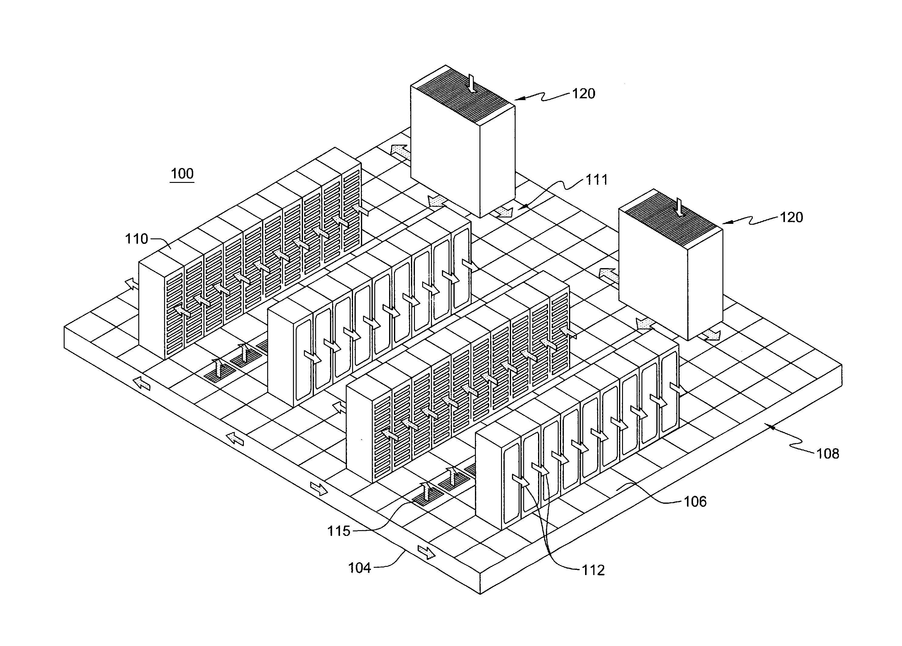
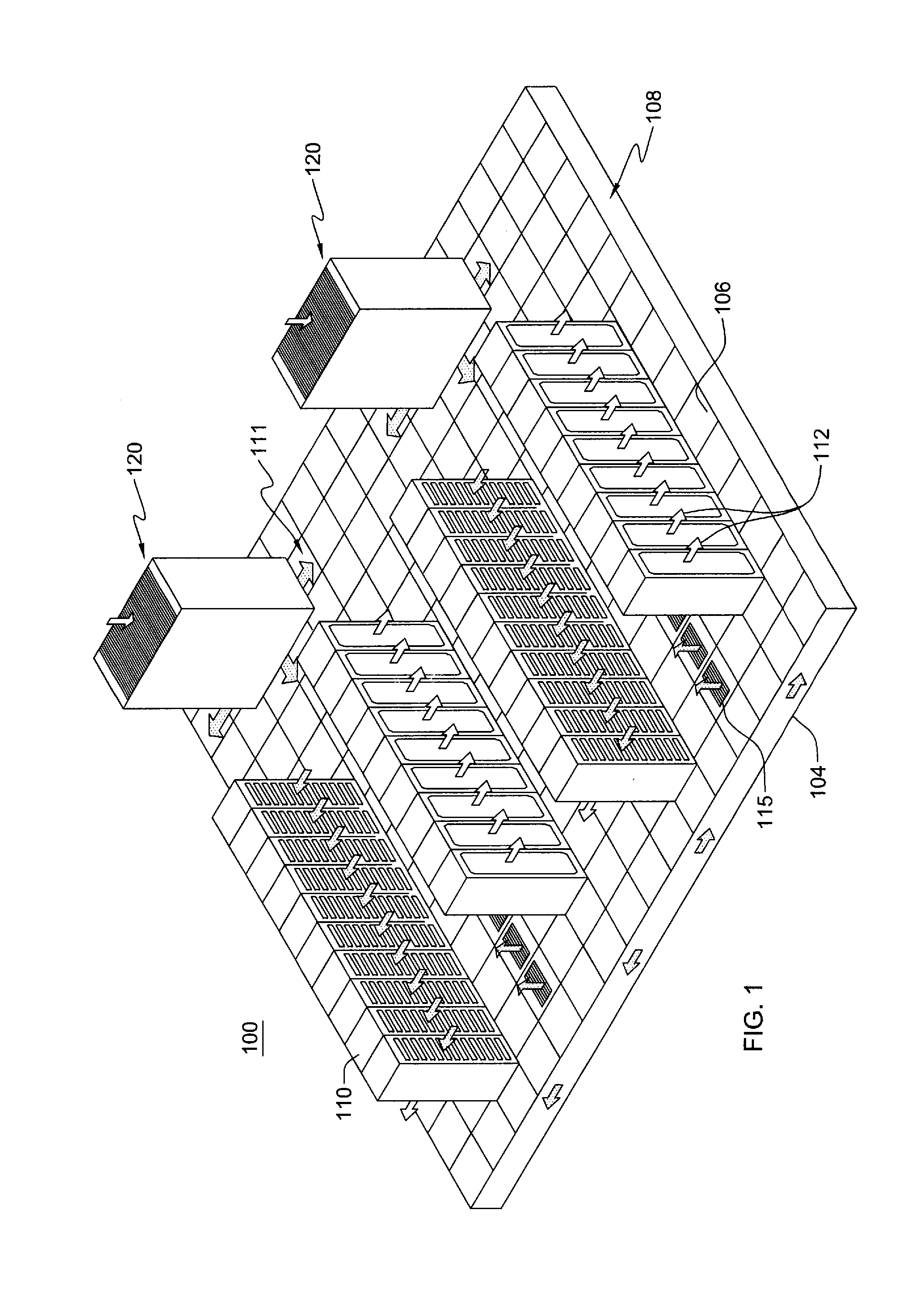
[0044]Computational fluid dynamics and heat transfer (CFD / HT) models may be used in the design and optimization of both new and existing data centers, as well as other bounded domains. Inviscid modeling has shown good speed advantages over the full Navier-Stokes CFD / HT models (over 20 times faster), but is incapable of capturing the physics of the viscous regions of the domain. A coupled inviscid-viscous solution method (CIVSM) or hybrid CFD / HT method for bounded domains is disclosed herein which increases both the solution speed and the accuracy of the CFD / HT model. The methodology includes an iterative solution technique that divides the full domain into multiple regions comprising, for instance, a set of viscous, inviscid and interface regions. The full steady, Reynolds-averaged Navier-Stokes equations with turbulence modeling may then be used to solve the viscous domain, while the inviscid domain may be solved using, for instance, potential flow equations or Euler equations. Onc...


PUM


Abstract

Computational fluid dynamics modeling of a bounded domain is provided which includes solving iteratively a computational fluid dynamics model of the bounded domain using mass flow boundary conditions that are specified. The solving includes automatically adjusting the specified mass flow boundary conditions for at least one iteration of the solving. The automatically adjusting includes mass balancing flows at a boundary of the bounded domain to provide corrected mass flow boundary conditions for the solving. The mass balancing includes applying different corrections to mass in-flow across the domain boundary, compared with mass out-flow across the boundary. The mass balancing may include multiplying mass in-flows across the boundary by (1−CF), and mass out-flows across the boundary by (1+CF), where CF is a determined correction factor, and net mass flow is positive for mass out-flow exiting the domain, and negative for mass in-flow entering the domain.

Description

STATEMENT REGARDING PRIOR DISCLOSURE BY THE INVENTOR OR A JOINT INVENTOR[0001]The following disclosure is submitted under 35 U.S.C. §102(b)(1)(A): “Coupled Inviscid-Viscous Solution Method for Bounded Domains: Application to Data-Center Thermal Management”, E. Cruz et al., publically available Feb. 13, 2015, in International Journal of Heat and Mass Transfer.BACKGROUND[0002]The heat dissipated by today's computing equipment is reaching levels that make it challenging to cool the computing equipment in densely-packed data centers. In data centers, the computing equipment, such as a multitude of computer servers, are commonly placed in a series of racks arranged in one or more rows in the data center. Typically, the data center has a cooling system that includes, by way of example, one or more air-conditioning units. The one or more air-conditioning units provide cooled air to the electronics racks via, for example, a sub-floor or overhead plenum and associated perforated tiles or dif...

Claims


Application Information

Patent Timeline
Patent Type & Authority Applications(United States)
IPC IPC(8): G06F17/50G06F17/10
CPCG06F17/10G06F17/5009G06F17/13H05K7/20836G06F2111/10G06F30/20
Inventor CRUZ, ETHAN E.
Owner IBM CORP
Why Eureka
Try Eureka