Operation display system, operation display apparatus, and operation display program
a display system and display device technology, applied in the direction of instruments, computing, electric digital data processing, etc., can solve the problems of difficult operation of touch panels with a high load reference, limited screen size, and difficulty in displaying all necessary information at a time, so as to reduce the burden of users
- Summary
- Abstract
- Description
- Claims
- Application Information
AI Technical Summary
Benefits of technology
Problems solved by technology
Method used
Image

Examples
first embodiment
Configuration of Operation Display System
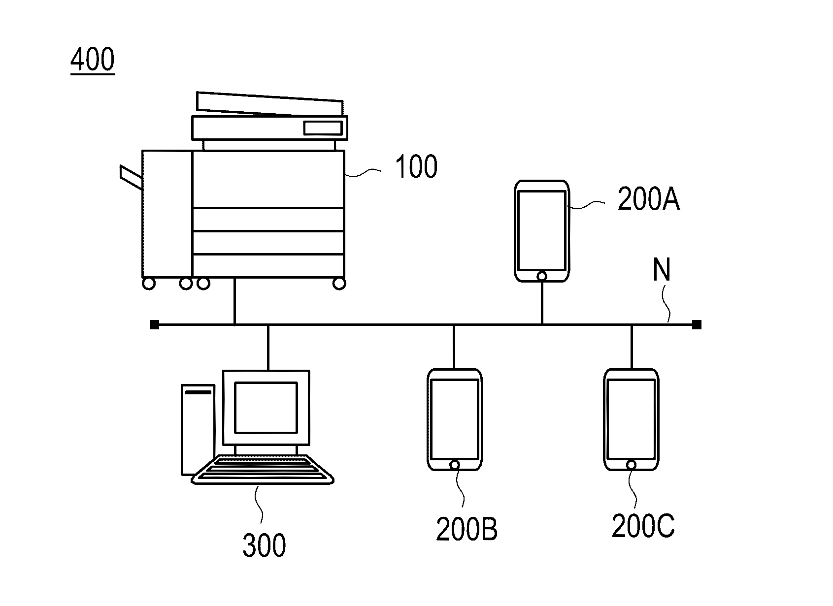
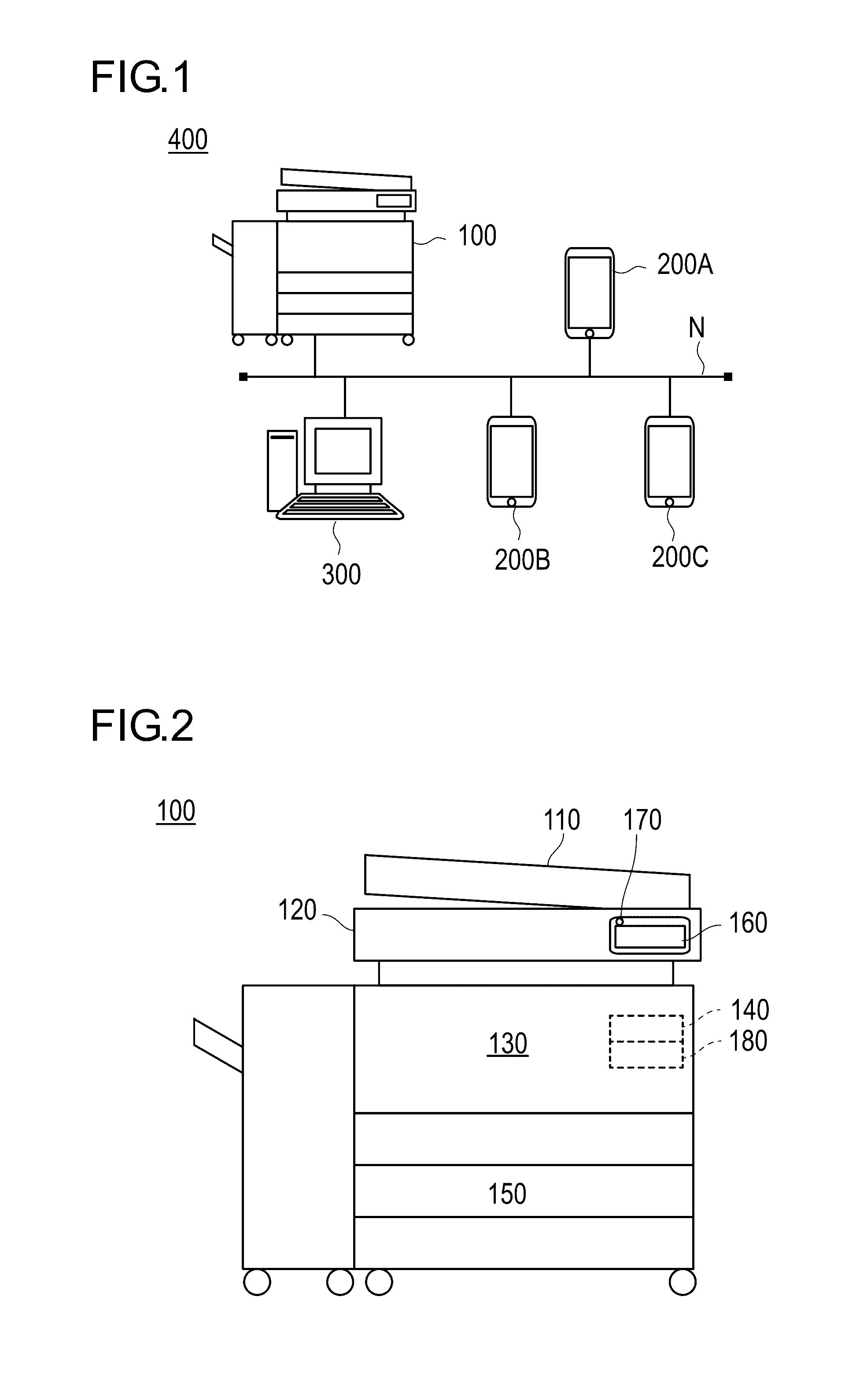
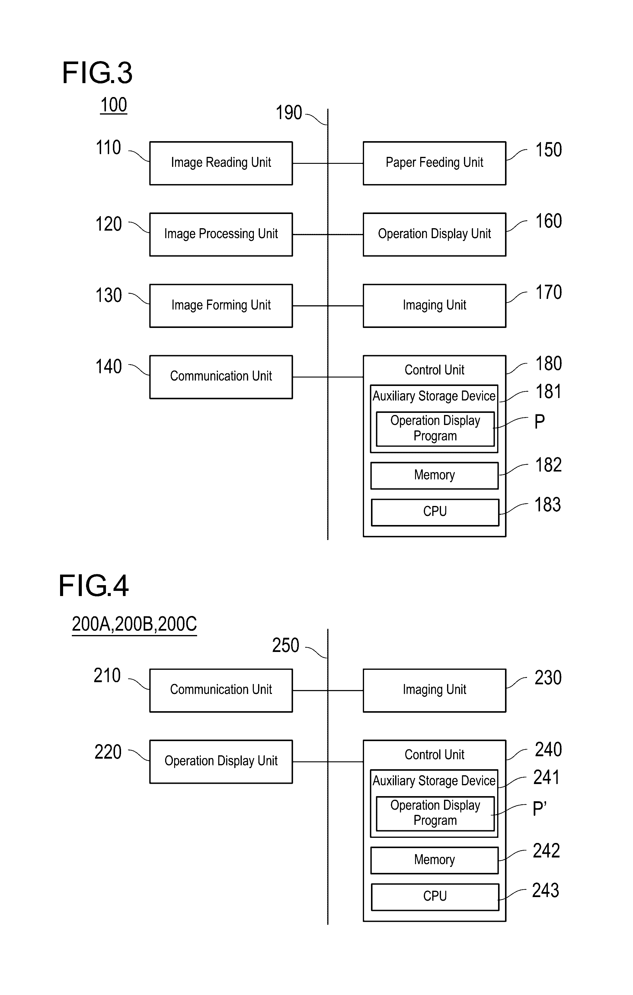
[0041]FIG. 1 is a schematic diagram for explaining a configuration of an operation display system of a first embodiment of the present invention. Furthermore, FIG. 2 and FIG. 3 are a side view and a block diagram for explaining a schematic configuration of an image forming apparatus illustrated in FIG. 1, respectively.
[0042]As illustrated in FIG. 1, an operation display system 400 has an image forming apparatus 100, portable terminal apparatuses 200A, 200B, and 200C, and a server 300. These elements are connected to an access point and are configured to be able to communicate with one another via a network N. In addition, the aforementioned elements may also be directly connected to one another without using the access point and the network. Furthermore, the aforementioned elements may also be connected to one another in a wireless manner, or in a wired manner.
[0043]The image forming apparatus 100 of the present embodiment, for example, may b...
second embodiment
[0127]In the first embodiment, the case has been described in which the degree of a change in pressing force for pressing touch panels between operation display apparatuses with different load references is notified.
[0128]In a second embodiment, the following description will be provided for the case in which as a result of a screen operation by a user between operation display apparatuses with different load references, when an operation object has been displayed across two operation display apparatuses, the operation object is moved to an apparatus with a weak load reference. Moreover, the following description will be provided for the case of notifying the degree of a change in pressing force for pressing touch panels. Hereinafter, in order to avoid a redundancy, a description of a configuration equal to that of the first embodiment will be omitted.
[0129]FIG. 10A is a flowchart for explaining one example of a processing procedure of an operation display method in the second embod...
third embodiment
[0152]In the second embodiment, the case has been described in which as a result of a screen operation by a user between operation display apparatuses with different load references, when an operation object has been displayed across them, the operation object is moved to an apparatus with a weak load reference. Furthermore, the case in which the degree of a change in pressing force for pressing a touch panel is notified has been described.
[0153]In a third embodiment, the following description will be provided for the case in which when an operation object has been displayed across operation display apparatuses with different load references, information on an operation of a touch panel is notified if a finger, etc., of a user have touched an operation object of each operation display apparatus. Moreover, the following description will be provided for the case in which the operation object is moved to an apparatus with a weak load reference when the finger, etc., of the user have to...
PUM
 Abstract
Description
Claims
Application Information
 - R&D
- Intellectual Property
- Life Sciences
- Materials
- Tech Scout
- Unparalleled Data Quality
- Higher Quality Content
- 60% Fewer Hallucinations
Browse by: Latest US Patents, China's latest patents, Technical Efficacy Thesaurus, Application Domain, Technology Topic, Popular Technical Reports.
© 2025 PatSnap. All rights reserved.Legal|Privacy policy|Modern Slavery Act Transparency Statement|Sitemap|About US| Contact US: help@patsnap.com