
Regulator with enhanced slew rate

a technology of slew rate and regulator, which is applied in the direction of amplifiers with impedence circuits, multiple input and output pulse circuits, and differential amplifiers, etc. it can solve the problems of increasing current consumption, critical malfunction of memory devices, so as to improve reduce current and power consumption, and improve the effect of slew rate and bandwidth

Active Publication Date: 2016-12-01
SK HYNIX INC
View PDF4 Cites 10 Cited by
  • Summary
  • Abstract
  • Description
  • Claims
  • Application Information

AI Technical Summary

Benefits of technology

The invention is about a regulator that improves the speed at which it can change the voltage it produces, while also reducing the amount of power consumed during this process. This makes it more efficient and effective for regulating the voltage.

Problems solved by technology

Late recovery of the regulator's output voltage may cause a critical malfunction in the memory device during different operations of a memory device (e.g., read, program, erase, data in, data out, and so forth).
However, the high slew rate and bandwidth will increase current consumption.
Moreover, there is a trade-off between gain and bandwidth, thus increasing bandwidth of the operational amplifier may reduce the gain of it.

Method used


Image

  • Regulator with enhanced slew rate
  • Regulator with enhanced slew rate
  • Regulator with enhanced slew rate

Examples


Embodiment Construction

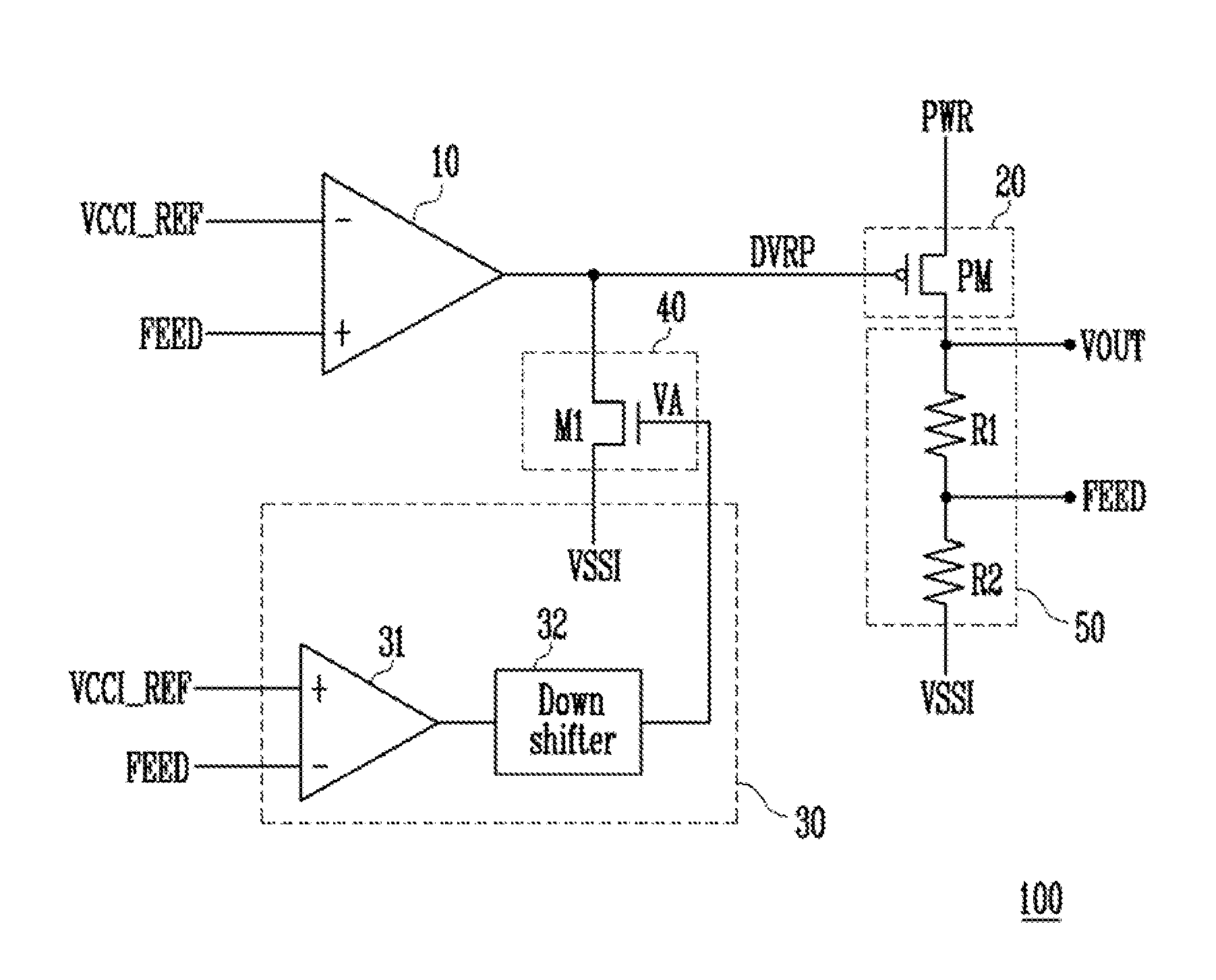
[0022]Exemplary embodiments of the present invention will be described in detail below with reference to the accompanying drawings. While the present invention is shown and described in connection with exemplary embodiments thereof, it will be apparent to those skilled in the art that various modifications may be made without departing from the spirit and scope of the invention. The terms and words used in the specification and claims should not be construed according to their ordinary or dictionary meaning. On the basis of the principle that the inventor may be define the appropriate meaning of a term in order to describe his / her own invention in the best possible way, a term should be construed according to a meaning that complies with the technical concept of the present invention. We also note that, detailed descriptions of well-known constructions in the relevant art may be omitted to avoid unnecessarily obscuring the present invention.

[0023]In the drawings corresponding featur...


PUM


Abstract

A regulator includes a first operational amplifier configured to receive a reference voltage and a feedback voltage and to output a node voltage based on a difference of the feedback voltage and the reference voltage; a first switch unit configured to receive the node voltage and to supply a recover current based on the node voltage; an output unit configured to output an output voltage and the feedback voltage according to a supply of the recover current; a comparison unit configured to receive the reference voltage and a feedback voltage and to sense a voltage drop of the output voltage; and a second switch unit configured to discharge the first switch unit according to the difference of the reference voltage and the feedback voltage.

Description

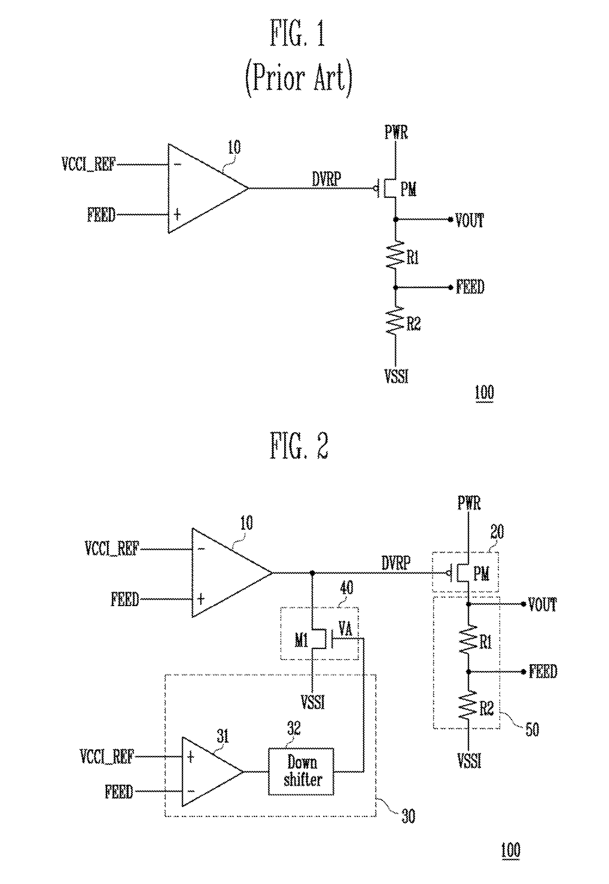
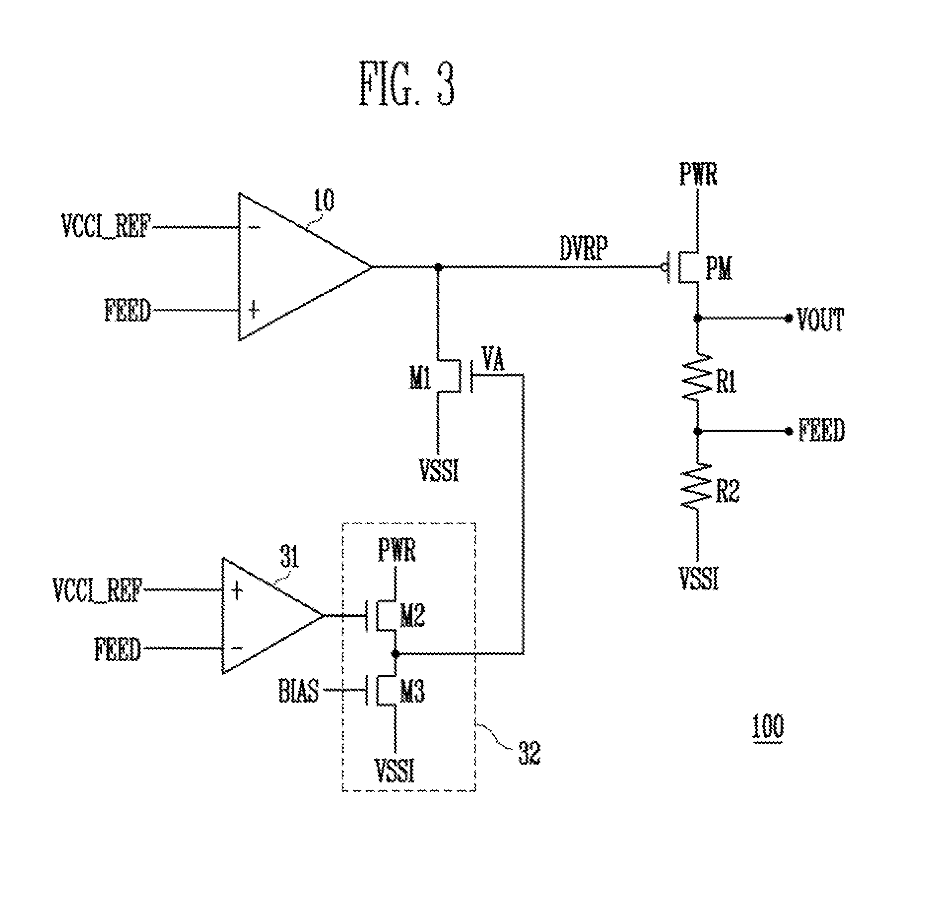
CROSS-REFERENCE TO RELATED APPLICATION[0001]The present application claims priority to Italian patent application No. 102015000018794 filed on May 28, 2015, which is incorporated herein by reference in its entirety.BACKGROUND[0002]1. Field[0003]The present disclosure relates to a regulator with enhanced slew rate.[0004]The disclosure particularly, but not exclusively, relates to a regulator with another feedback network therein.[0005]2. Description of the Related Art[0006]A low-dropout (LDO) regulator is a DC linear voltage regulator which may be regulate an output voltage even when a supply voltage is very close to, the output voltage. Advantages of the LDO regulator over other DC to DC regulators include lower switching noise, smaller device size, and greater design simplicity,[0007]FIG. 1 schematically shows a circuit diagram of a conventional LDO regulator 100. The LDO regulator 100 includes an operational amplifier 10, a PMOS transistor PM, a first resistor R1, and a second res...

Claims


Application Information

Patent Timeline
Patent Type & Authority Applications(United States)
IPC IPC(8): G05F1/575H03F3/45H03K5/24H03F3/50
CPCG05F1/575H03F3/505H03F2200/69H03K5/24H03F3/45071H03F3/45183H03F2203/45248G05F1/573G05F1/618G05F1/62
Inventor CARACCIOLO, HERVE'
Owner SK HYNIX INC
Learn More