
Method and apparatus for detecting a gas pocket using ultrasound

a gas pocket and ultrasound technology, applied in the field of ultrasonic imaging, can solve the problems of difficult detection of intraperitoneal free air, difficult for emergency physicians to identify all gas pockets, and long time-consuming for non-experienced users to identify this kind of sign

Active Publication Date: 2016-12-01
KONINKLJIJKE PHILIPS NV
View PDF8 Cites 13 Cited by
  • Summary
  • Abstract
  • Description
  • Claims
  • Application Information

AI Technical Summary

Benefits of technology

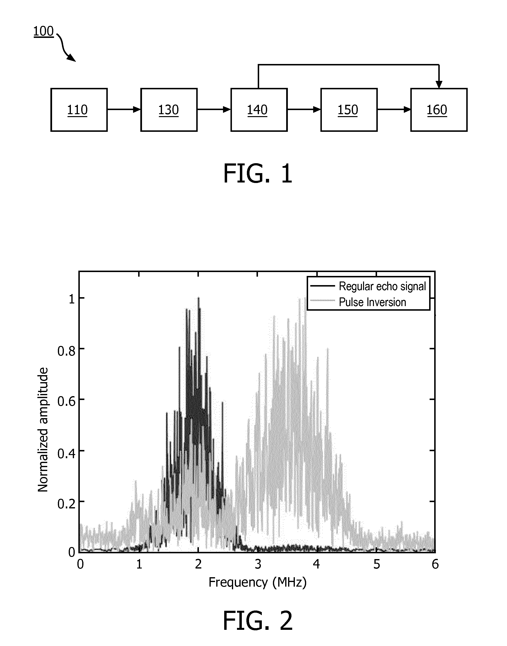
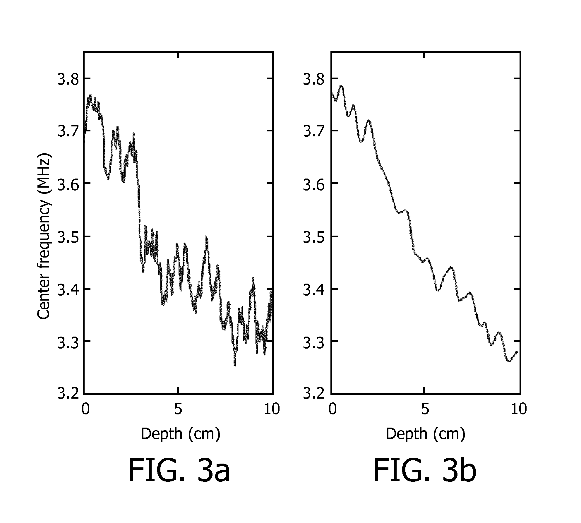
The present invention provides an improved method and apparatus for detecting gas pocket in a region-of-interest (ROI) using ultrasound technology. The method involves obtaining the second harmonic component of the ultrasound echo signal reflected from the ROI and analyzing its change with depth to detect the gas pocket. The second harmonic component indicates the trend of the center frequency along with a plurality of depths, making it more reliable than the decrease in center frequency at a depth. The method can be used with both pulse inversion technique and band-pass filtering approach, which provides increased frame rate and less sensitivity to motion artifacts. The smoothening over a number of ultrasound scanning lines helps reduce undesirable distortions caused by noises and disturbances.

Problems solved by technology

It takes a long time for non-experienced users to identify this kind of sign (EPSS) from ultrasound images.
It is really difficult for emergency physicians to identify all gas pockets in an examination time of around 5 minutes for the whole abdomen even if they know the optimal probe position for detecting intraperitoneal free air after blunt abdominal trauma in the right paramedian epigastric area in the longitudinal direction.
However, the detection of intraperitoneal free air might be difficult even for an experienced sonographer in emergency situations under difficult patient conditions.
Such existing approaches are time-consuming and the accuracy is very dependent on the operator's experience.

Method used


Image

  • Method and apparatus for detecting a gas pocket using ultrasound
  • Method and apparatus for detecting a gas pocket using ultrasound
  • Method and apparatus for detecting a gas pocket using ultrasound

Examples


Embodiment Construction

[0040]The present invention will be described with respect to particular embodiments and with reference to certain drawings but the invention is not limited thereto but only by the claims. The drawings described are only schematic and are non-limiting. In the drawings, the size of some of the elements may be exaggerated and not drawn to scale for illustrative purposes.

[0041]FIG. 1 shows a schematic diagram of an ultrasound system 100 for detecting a gas pocket in a Region-of-Interest (ROI) in accordance with an embodiment of the present invention. As shown in FIG. 1, the ultrasound system 100 includes an ultrasound probe 110 for transmitting an ultrasound signal toward the ROI and acquiring an ultrasound echo signal reflected from the ROI. The ultrasound echo signal may be pre-processed to reduce noise and / or motion artifacts.

[0042]The pre-processed signals are coupled to an obtaining unit 130. The obtaining unit 130 is configured to obtain a second harmonic component of the ultraso...


PUM


Abstract

Existing gas pocket detection approaches are based on visual observations of B-mode ultrasound images showing comparisons between normal soft tissue and gas pockets, which are time-consuming and dependent on operator experience. The present invention proposes an ultrasound system and a method of detecting a gas pocket. The ultrasound system comprises: an ultrasound probe (110) for transmitting an ultrasound signal toward the ROI and acquiring an ultrasound echo signal reflected from the ROI along a plurality of scanning lines; an obtaining unit (130) for obtaining a second harmonic component of the ultrasound echo signal for each depth of a plurality of depths along each scanning line of the plurality of scanning lines; and a deriving unit (140) for deriving a change in a center frequency of the second harmonic component along with the depth.

Description

FIELD OF THE INVENTION[0001]The present invention relates to ultrasound imaging, particularly to a method and an apparatus for detecting a gas pocket using ultrasound.BACKGROUND OF THE INVENTION[0002]Trauma is the leading cause of death in the United States for men and women under the age of 45 years and the fourth overall cause of death for all ages. Trauma also has a substantial economic impact on the health care system, accounting for over one-third of all emergency department visits and resulting in over $80 billion per year in direct medical care cost, for example, in 2007, over 180 000 people died of trauma, and abdominal injuries contributed to a large number of these deaths.[0003]Pneumoperitoneum is a condition in which a free gas pocket or tiny amount of free gas or air is trapped within the abdominal cavity but not contained in a hollow viscus. Identifying abnormal intra-abdominal gas pockets or collections may be critically important in establishing an accurate diagnosis....

Claims


Application Information

Patent Timeline
Patent Type & Authority Applications(United States)
IPC IPC(8): A61B8/08A61B8/14G01S7/52A61B8/00
CPCA61B8/0833A61B8/469A61B8/5223G01S7/52038A61B8/14A61B8/461A61B8/5207A61B8/48A61B8/00A61B8/467A61B8/46A61B8/52A61B8/5215
Inventor XU, JINGPINGRAJU, BALASUNDAR IYYAVUHUANG, SHENG-WENWANG, SHOUGANGRADULESCU, EMIL GEORGEZHOU, SHIWEI
Owner KONINKLJIJKE PHILIPS NV
Learn More