
Video generating method and apparatus of video generating system

Active Publication Date: 2016-11-24
SZ REACH TECH
View PDF1 Cites 9 Cited by
  • Summary
  • Abstract
  • Description
  • Claims
  • Application Information

AI Technical Summary

Benefits of technology

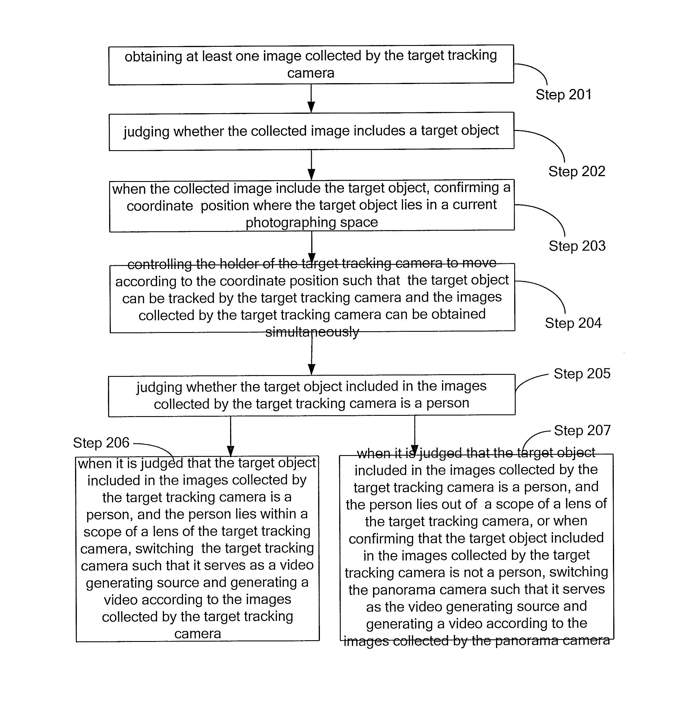
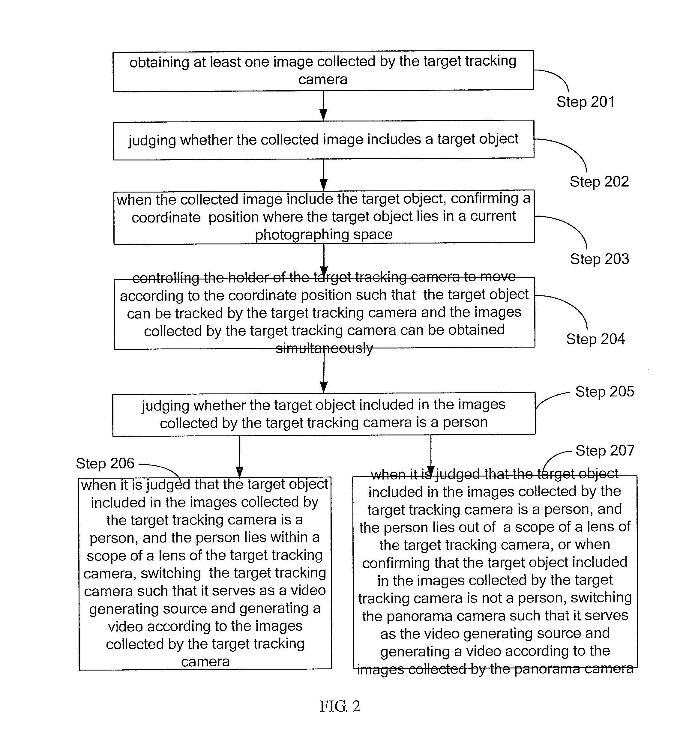
The present invention allows for automatic switching between different cameras when recording videos. This eliminates the need for manual intervention and ensures smoothly switched videos. This system uses a target tracking camera to confirm the position of the target object and determine if it is a person. If the person is within the scope of the target tracking camera, it automatically switches to the target tracking camera for video generation. If the person is out of the scope of the target tracking camera, the system automatically switches to a panorama camera for video generation. This ensures that different cameras are always utilized for video recording, resulting in better video quality.

Problems solved by technology

In an existing camera system, switching between a distant view and a nearby view for a single camera or switching among different cameras is usually controlled by manual methods, thus, at least one person is needed for being on duty during a video generating process, and operational errors may be brought during manual switching processes.
To sum up, the prior art can't achieve intelligent switching for recording and broadcasting among different cameras during processes of tracking targets and generating videos through the cameras.

Method used


Image

  • Video generating method and apparatus of video generating system
  • Video generating method and apparatus of video generating system
  • Video generating method and apparatus of video generating system

Examples


first embodiment

The First Embodiment

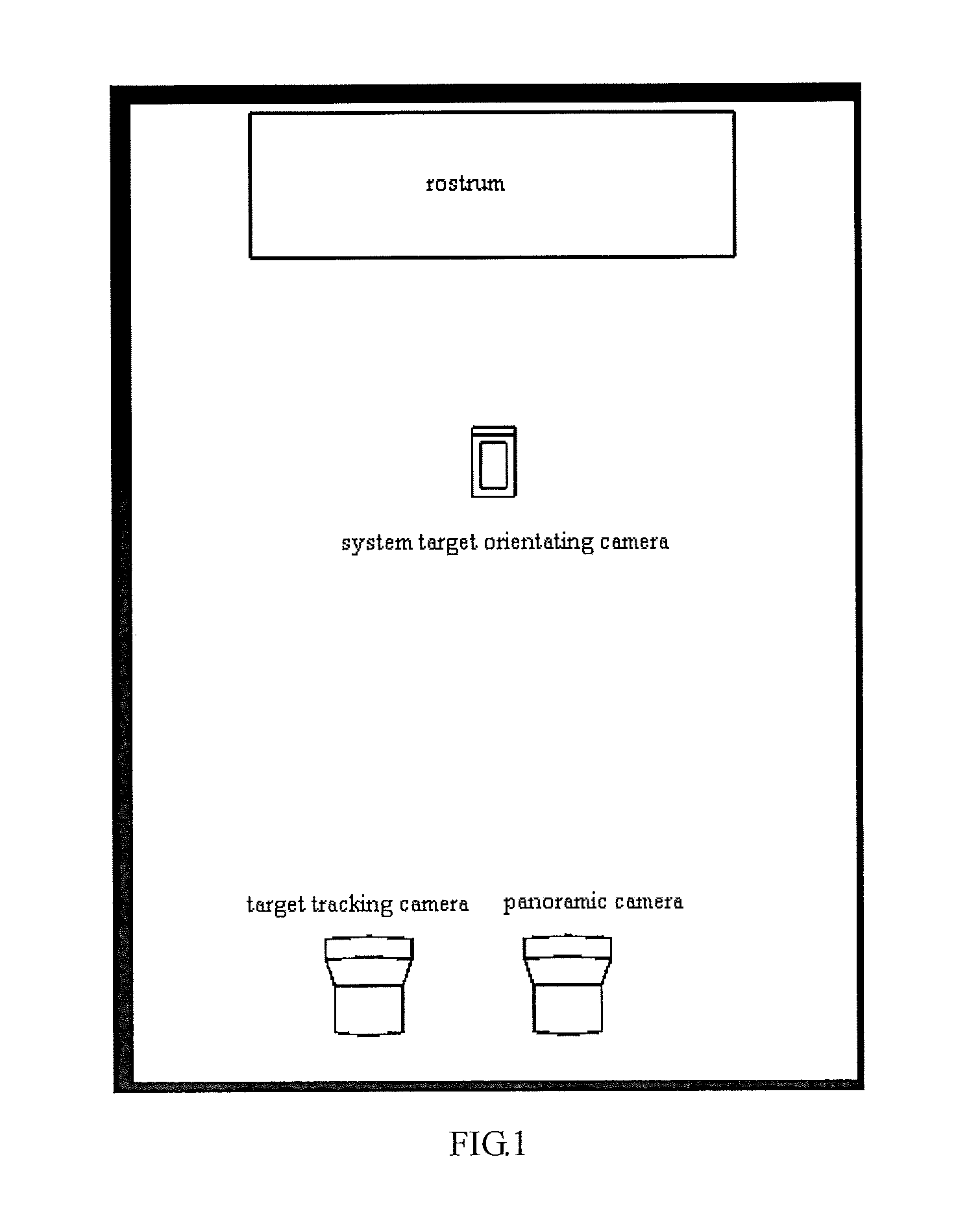
[0031]FIG. 2 illustrates a flow chart of the implementation of a video generating method of the video generating system provided by the first embodiment of the present invention, the video generating system comprises a system target orientating camera, a target tracking camera and a panoramic camera, wherein, a suspicious object can be found via the system target orientating camera, images can be collected via the system target orientating camera and the target tracking camera and image analysis for the images can be performed to confirm whether the suspicious object is a person, by which the disturbances caused by other objects can be excluded, and images collected from different cameras can be controlled to be automatically switched and thereby generate a video, so that accurate tracking and switching for a target are realized. The method is explained in detail as follows:

[0032]step 201, obtaining at least one image collected by the system target orientating ca...

second embodiment

The Second Embodiment

[0041]FIG. 2 illustrates a flow chart of the implementation of the video generating method of the video generating system provided by the second embodiment of the present invention, the video generating system comprises a system target orientating camera, a target tracking camera and a panoramic camera, the method is described in detail as follows:

[0042]step 301, obtaining at least one image collected by the system target orientating camera;

[0043]step 302, comparing image frames of the images currently collected by the system target orientating camera with background frames, when the number of variable pixels in a currently obtained image exceeds a predetermined pixel number threshold value, judging that the current image includes a foreground object, wherein, the background frame is considered as an initial frame of the image collected by the system target orientating camera;

[0044]wherein, the background frame is an image frame which includes foreground object,...

third embodiment

The Third Embodiment

[0068]FIG. 4 illustrates a structural block diagram of a video generating apparatus provided by the third embodiment of the present invention, for convenient explanation, only the parts related to the embodiments of the present invention are illustrated.

[0069]The video generating apparatus of the video generating system comprises: an obtaining unit 41, a first judging unit 42, a position confirming unit 43, a tracking unit 44, a second judging unit 45, a first switching unit 46 and a second switching unit 47.

[0070]The obtaining unit 41 is configured for obtaining at least one image collected by a system target orientating camera;

[0071]the first judging unit 42 is configured for judging whether the image collected by the system target orientating camera includes a target object;

[0072]the position confirming unit 43 is configured for confirming a coordinate position where the target object lies in a current photographing space when the collected image includes the ...


PUM


Abstract

The present invention belongs to the technical field of video recording and provides a video generating method and apparatus of a video generating system, the video generating system comprises a system target orientating camera, a target tracking camera and a panorama camera, the method comprises: when it is judged that a target object included in the image collected by the target tracking camera is a person, and the person lies within a scope of a lens of the target tracking camera, switching the target tracking camera such that it serves as a video generating source and generating a video according to images collected by the target tracking camera; when it is judged that the target object included in an image collected by the target tracking camera is a person, and the person lies out of the scope of the lens of the target tracking camera, or it is judged that the target object included in an image collected by the target tracking camera is not a person, switching the panorama camera such that it serves as the video generating source and generating a video according to the images collected by the panorama camera. Automatic control for switching among different cameras to collect images and generate videos is achieved, so that accurate tracking for any target object and accurate switching among different cameras can be done, and automatic switching among different cameras during a video generating process is realized; in this way, there is no need to perform operation and manual intervention after installation and debugging are accomplished.

Description

TECHNICAL FIELD[0001]The present application relates to the technical field of video recording, and more particularly, relates to a video generating method and apparatus of a video generating system.BACKGROUND[0002]With the development of technology and the progress of the society, using a camera system to track an object and generates a video has already been universal. In an existing camera system, switching between a distant view and a nearby view for a single camera or switching among different cameras is usually controlled by manual methods, thus, at least one person is needed for being on duty during a video generating process, and operational errors may be brought during manual switching processes.[0003]To sum up, the prior art can't achieve intelligent switching for recording and broadcasting among different cameras during processes of tracking targets and generating videos through the cameras.BRIEF SUMMARY[0004]A purpose of the present application is to provide a video gene...

Claims


Application Information

Patent Timeline
IPC IPC(8): H04N5/232G06K9/00G06T7/00G06T7/20H04N5/247H04N5/268
CPCH04N5/23219H04N5/23245H04N5/23296H04N5/247H04N5/268G06T2207/30201G06T7/2006G06T7/2093G06K9/00221G06T2207/10016G06T7/004G06T2207/30196G06T7/254G06V40/16H04N23/45H04N23/61H04N23/611H04N23/90H04N23/69H04N23/667
Inventor QU, XINLIAO, HAISUN, XINGLEIYUAN, JIEXU, CHONGQIAN, ZHEN
Owner SZ REACH TECH
Learn More