
Display device, method of controlling the same, and game machine

Inactive Publication Date: 2007-02-15
SEIKO EPSON CORP
View PDF4 Cites 7 Cited by
  • Summary
  • Abstract
  • Description
  • Claims
  • Application Information

AI Technical Summary

Benefits of technology

[0011] An advantage of some aspects of the invention is that it provides a display device capable of smoothly switching the visual brightness of a displayed image at the time of switching between a three-dimensional image and a two-dimensional image, while displaying a two-dimensional image that has high brightness and is easy to view, a method of controlling the display device, and a game machine provided with the display device.

Problems solved by technology

However, the three-dimensional display devices (JP-A-11-103475 and ‘Step barrier system multi-view glass-less 3-D display’) do not disclose switching between a three-dimensional image and a two-dimensional image and various display methods using the switching between the three-dimensional image and the two-dimensional image.
However, the lenticular lens or the image splitter makes it difficult to view the two-dimensional image.
In particular, when the image splitter is used, even in the two-dimensional image display, the image splitter continuously shield light, and thus light is not effectively used.

Method used


Image

  • Display device, method of controlling the same, and game machine
  • Display device, method of controlling the same, and game machine
  • Display device, method of controlling the same, and game machine

Examples


first embodiment

[0036] Hereinafter, a game machine according to a first embodiment of the invention will be described in detail with reference to the accompanying drawings.

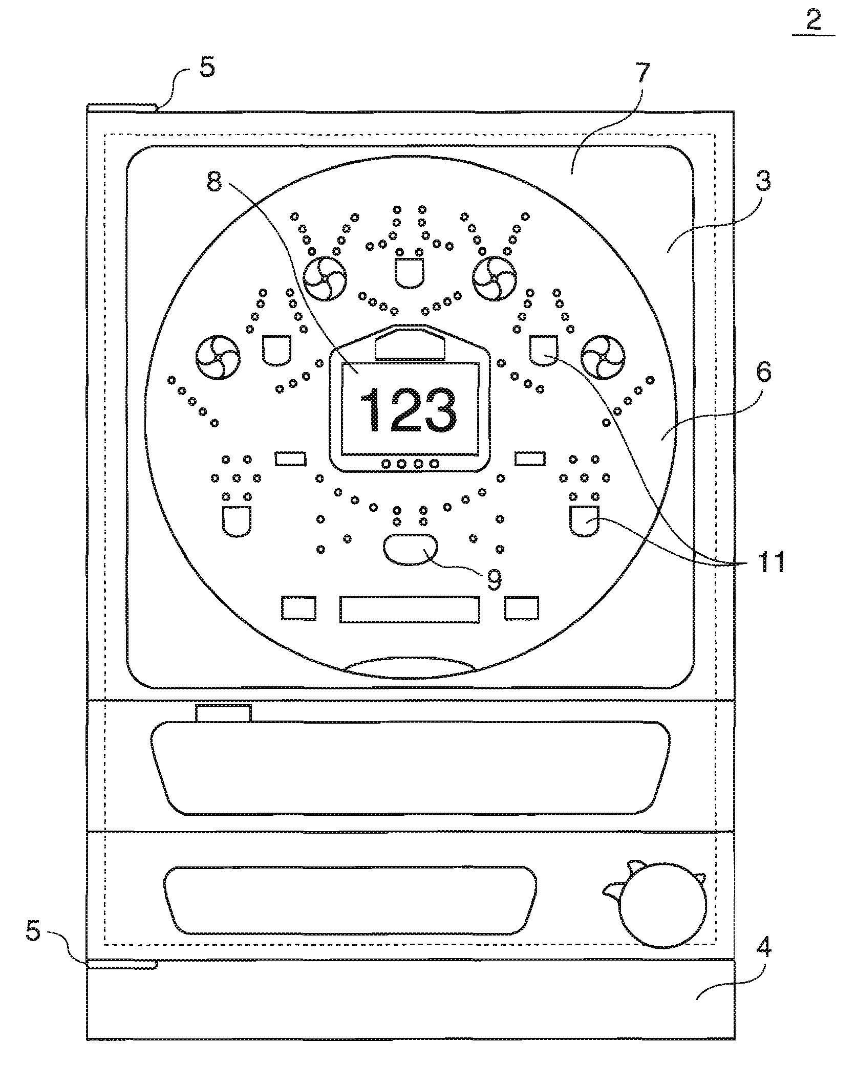
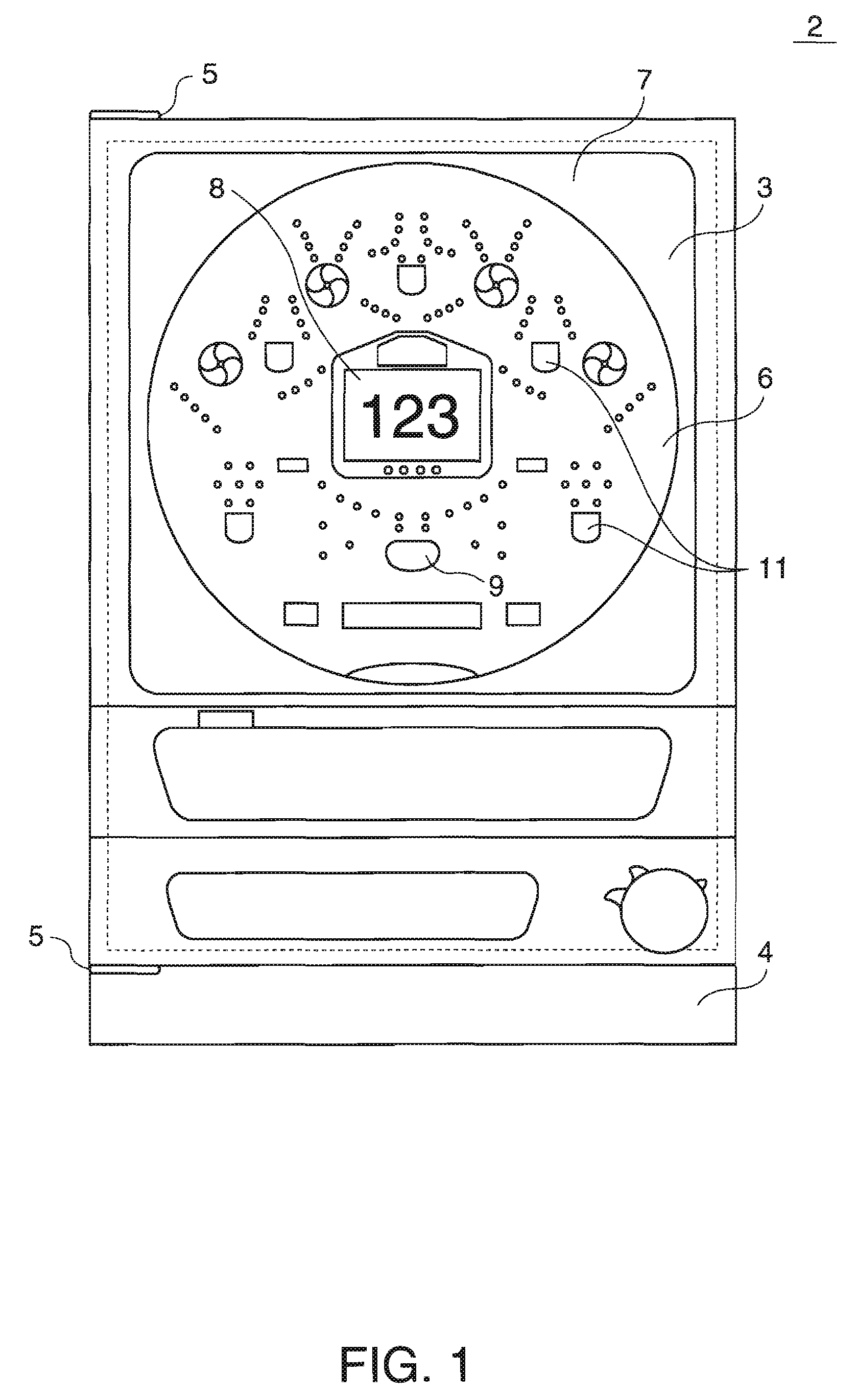
[0037]FIG. 1 is a front view illustrating the game machine according to the first embodiment. A game machine 2 shown inFIG. 1 is a Japanese pinball game machine, and includes a front frame 3, a main frame 4, and a game board 6. The front frame 3 is openably mounted to the external main frame 4 through a hinge 5. The game board 6 is housed in a housing frame. The housing frame is mounted to the rear surface of the front frame 3. A cover glass 7 covering the front surface of the game board 6 is mounted to the front frame 3.

[0038] A game area surrounded by a guide rail is formed on the surface of the game board 6, and an image display device 8, which is a special pattern display device, is provided substantially at the center of the game area. The image display device 8 can display a left-eye image component and a right-eye image ...

second embodiment

[0066] Next, a game machine according to a second embodiment of the invention will be described. The game machine according to the second embodiment has a display control device 70 that is different from that of the game machine according to the first embodiment in structure. In this embodiment, components not described herein have the same structure as those in the first embodiment.

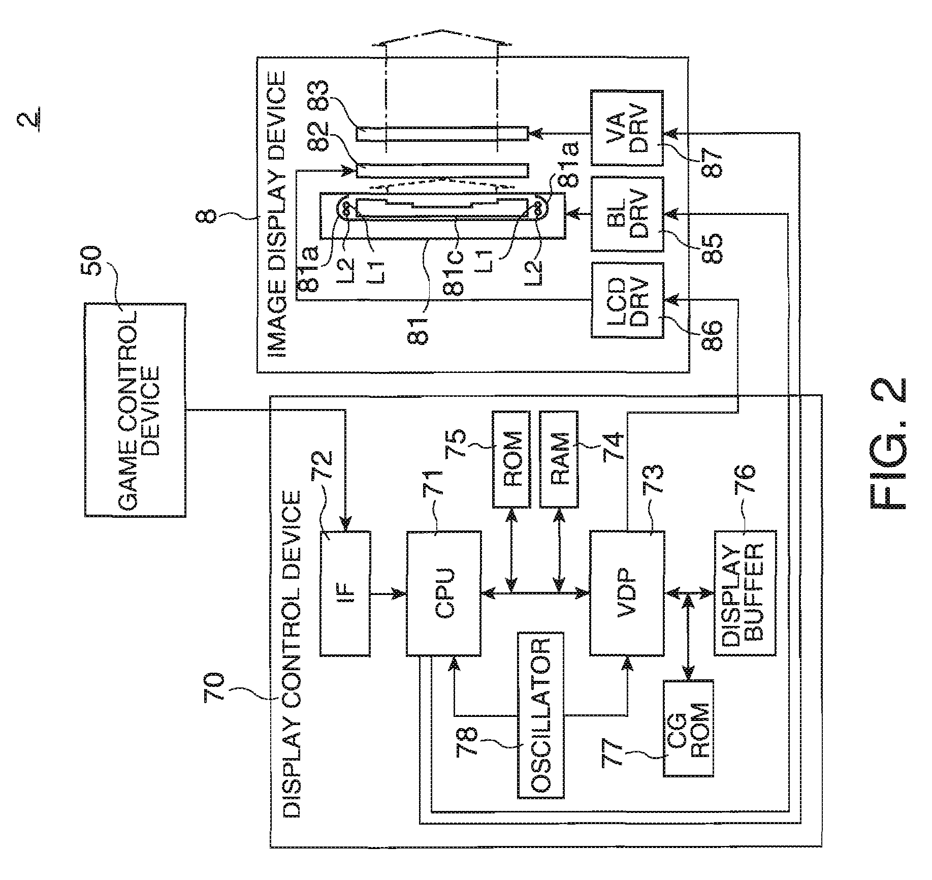
[0067]FIG. 10A is a flow chart illustrating the operation of the display control device 70 and an image display device 8. More specifically, FIG. 10A shows the control of the illuminance of illumination light when a two-dimensional image is switched to a three-dimensional image. In this case, an adjustment signal output from the CPU 71 to the illuminating device 81 leads a switching signal output from the CPU 71 to the LCD barrier 83 by a response time difference, and the switching signal output to the LCD barrier 83 gradually increases continuously or step by step. First, the image display device 8 ope...


PUM


Abstract

A display device includes: a display unit having an illuminating device that emits illumination light, a display panel that has an image display region where a two-dimensional image is formed by a light modulating device for modulating the illumination light, and a barrier that is arranged opposite to the image display region and performs switching between an operational state in which a three-dimensional image is displayed and a non-operational state in which the three-dimensional image is not displayed; and a control unit that adjusts illuminance of the illumination light incident on the display panel when the barrier is switched from the non-operational state to the operational state and / or when the barrier is switched from the operational state to the non-operational state.

Description

BACKGROUND [0001] 1. Technical Field [0002] The present invention relates to a display device suitably incorporated into a game machine, such as a Japanese pinball game machine, a slot machine, or an arcade game machine, and more particularly, to a display device capable of performing three-dimensional display to a viewer, a method of controlling the display device, and a game machine including the display device. [0003] 2. Related Art [0004] There has been proposed a three-dimensional display device in which a parallax barrier is arranged on the viewer side of a color liquid crystal panel, and a right-eye image line and a left-eye image line are alternately displayed on a display screen of the color liquid crystal panel (see JP-A-11-103475). In this case, a second color filter is provided between a backlight and the color liquid crystal display panel so as to be reversely arranged to a color filter of the color liquid crystal panel, thereby improving the color purity of the color l...

Claims


Application Information

Patent Timeline
IPC IPC(8): G09G5/02A63F7/02
CPCH04N13/0454H04N13/0409H04N13/31H04N13/359
Inventor TSUKAGOSHI, SHINICHIMORIYAMA, YOSHIYUKIMIYAZAWA, TAKAYUKI
Owner SEIKO EPSON CORP
Learn More