
Synchronization signal generating apparatus and video signal processing apparatus

Inactive Publication Date: 2006-08-24
PANASONIC CORP
View PDF3 Cites 0 Cited by
  • Summary
  • Abstract
  • Description
  • Claims
  • Application Information

AI Technical Summary

Benefits of technology

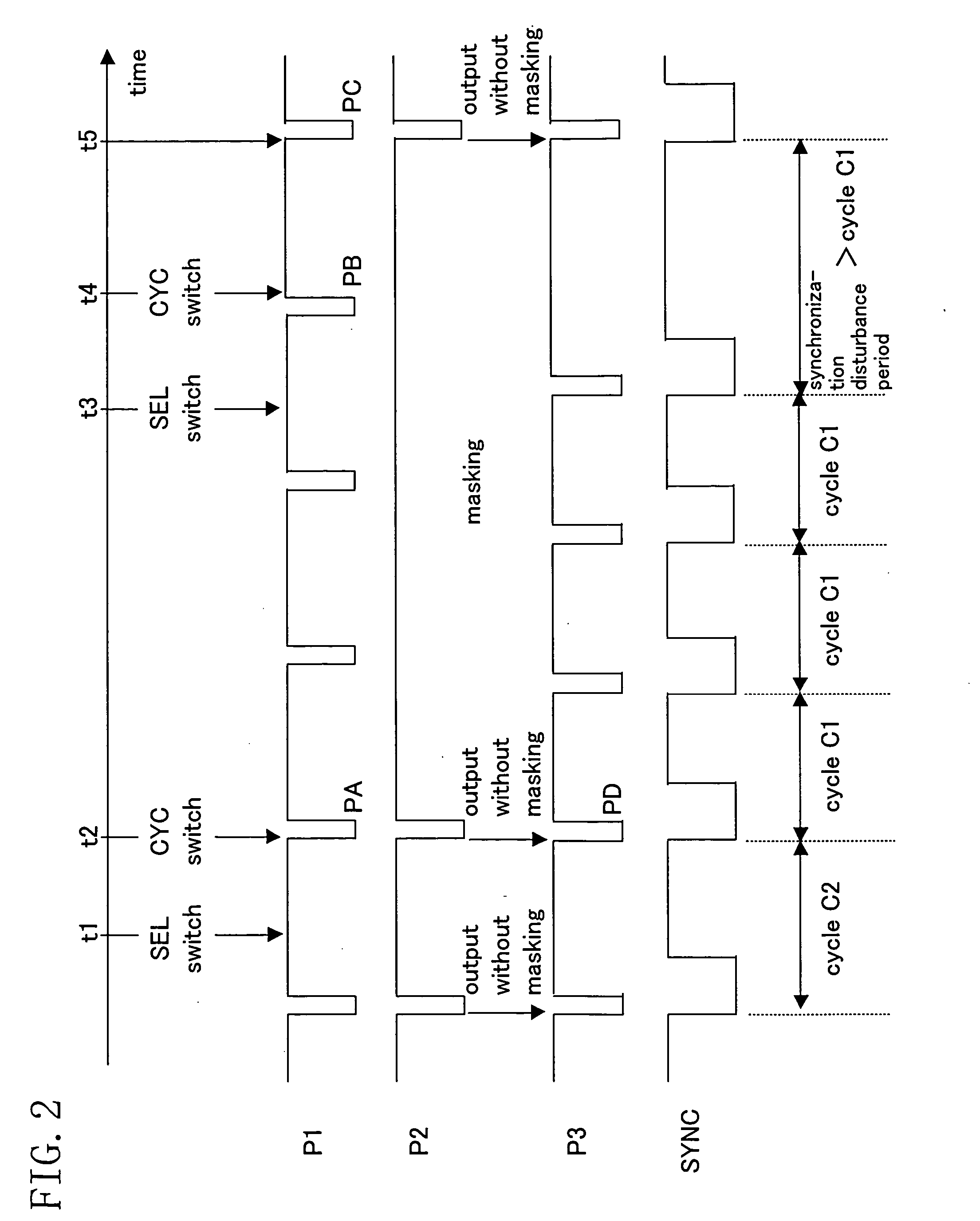
[0012] In view of the above-described problems, an object of the present invention is to provide a synchronization signal generating apparatus which suppresses a synchronization disturbance when an unstable synchronization signal is switched to an independent synchronization signal, and thereafter, the synchronization signal is switched to the original synchronization signal.
[0025] As described above, according to the present invention, when an independent synchronization signal during unstable synchronization and a synchronization signal during stable synchronization are switched, the occurrence of a synchronization signal having a short synchronization period, which is responsible for a malfunction of various video apparatuses, is suppressed, so that the synchronization signals can be smoothly switched.

Problems solved by technology

However, in this synchronization signal generating apparatus, when synchronization signals are switched, a discontinuity occurs in the synchronization signal.
The discontinuity of synchronization disturbs processes of various video apparatuses.
Particularly, a synchronization signal having a short synchronization period often causes a large disturbance, leading to significant noise in displayed video.
In addition, it is likely that a synchronization signal having a short synchronization period, which is particularly problematic, occurs.
As a result, a malfunction occurs, depending on the degree of the unstable state and the video apparatus.

Method used


Image

  • Synchronization signal generating apparatus and video signal processing apparatus
  • Synchronization signal generating apparatus and video signal processing apparatus
  • Synchronization signal generating apparatus and video signal processing apparatus

Examples


first embodiment

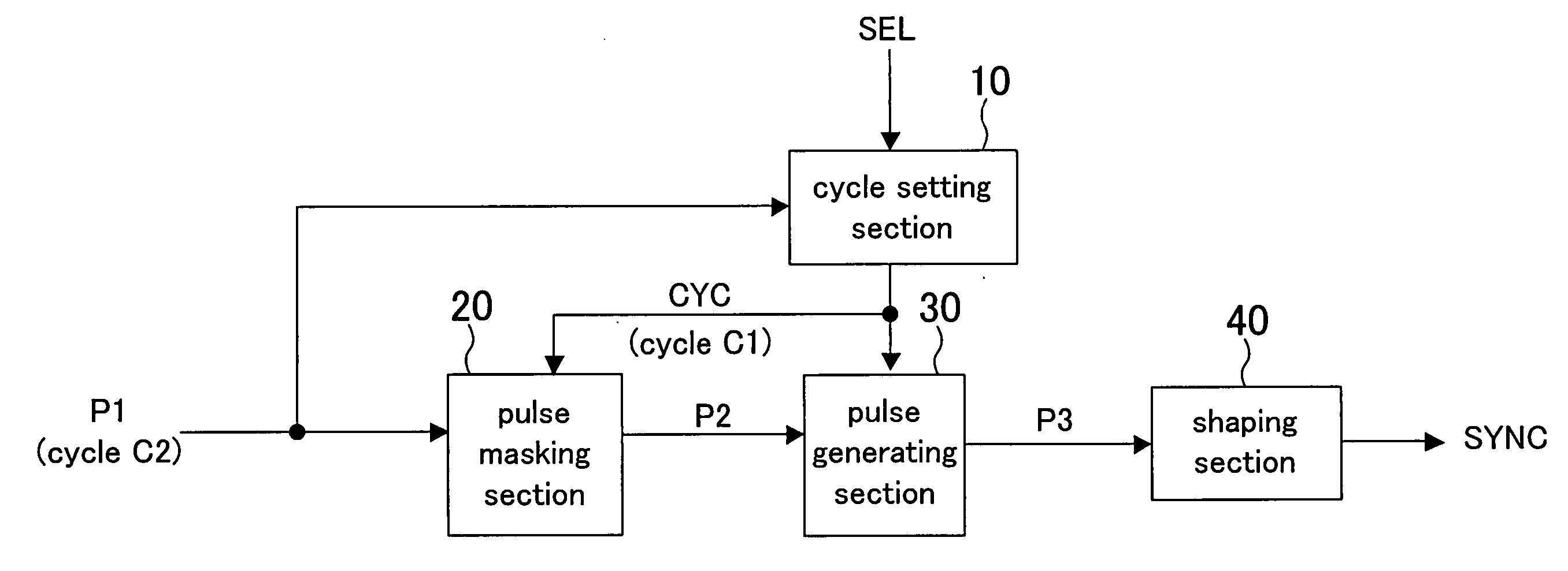
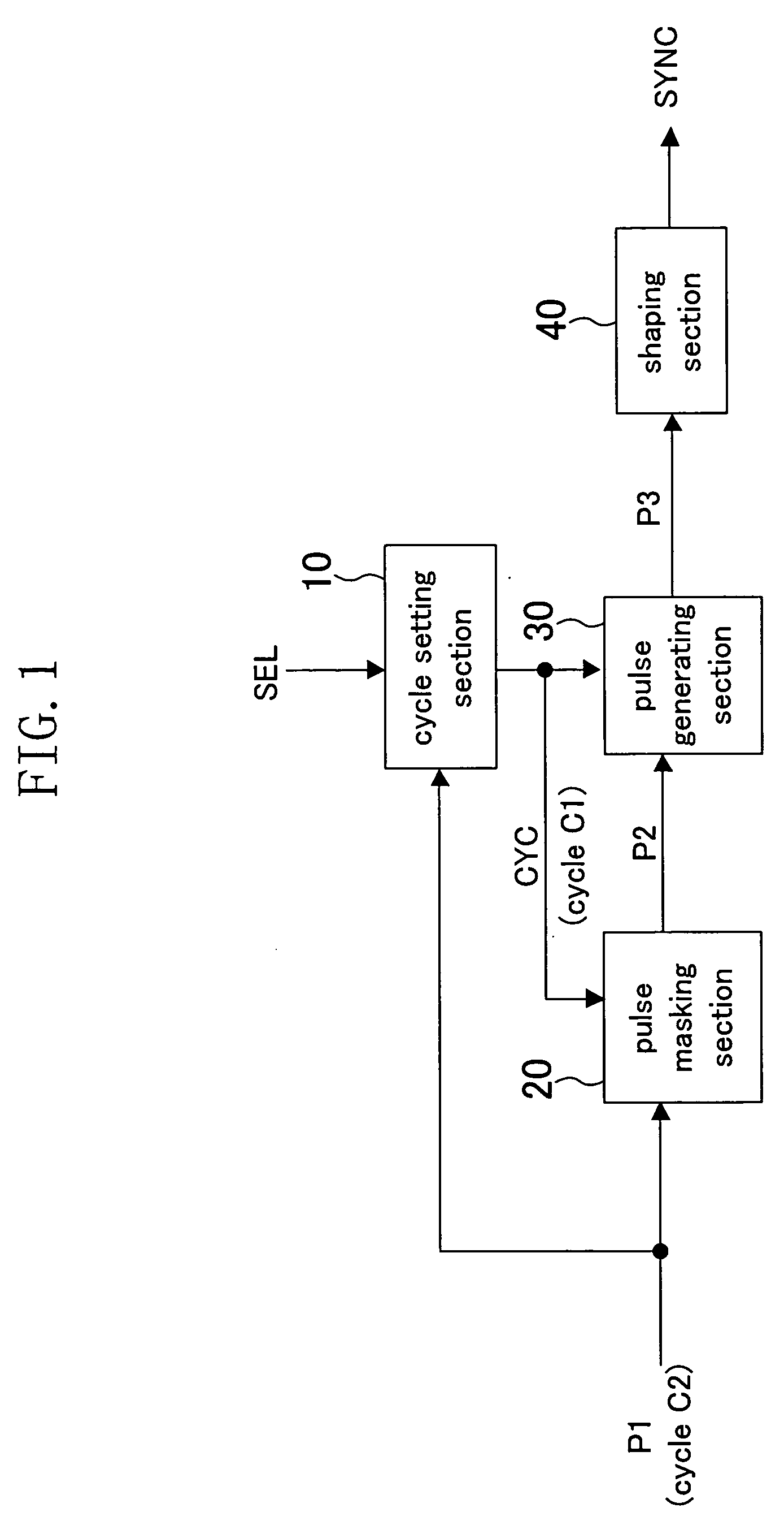
[0042]FIG. 1 illustrates a structure of a synchronization signal generating apparatus according to a first embodiment. The synchronization signal generating apparatus of this embodiment comprises a cycle setting section 10, a pulse masking section 20, a pulse generating section 30, and a shaping section 40. The cycle setting section 10 outputs cycle information CYC indicating a cycle C1. The pulse masking section 20 outputs a pulse train P2 based on both a pulse train P1 and the cycle information CYC. The pulse train P1 corresponds to the synchronization signal SYNC1 in the conventional synchronization signal generating apparatus of FIG. 12. Specifically, the pulse masking section 20 outputs the pulse train P1 as the pulse train P2 when C1>C2 where C2 denotes the cycle of a pulse of the pulse train P1, and outputs a signal obtained by masking pulse(s) in the pulse train P1 as the pulse train P2 when C1≦C2. The pulse generating section 30 outputs a pulse train P3 based on both the pu...

second embodiment

[0052]FIG. 3 illustrates a structure of a synchronization signal generating apparatus according to a second embodiment. The synchronization signal generating apparatus of this embodiment comprises a cycle setting section 10A, a pulse masking section 20, a pulse generating section 30, and a shaping section 40A. The pulse masking section 20 and the pulse generating section 30 are similar to those of the first embodiment and will not be described. Hereinafter, the cycle setting section 10A and the shaping section 40A will be particularly described.

[0053] The cycle setting section 10A switches cycle information CYC based on both a pulse train P3 and a cycle selection signal SEL. Specifically, when the cycle selection signal SEL indicates selection of a decrease in the cycle C1, the cycle setting section 10A switches the cycle information CYC to information indicating the cycle C1 selected using the cycle selection signal SEL upon receiving a pulse of the pulse train P3 for the first ti...

third embodiment

[0062]FIG. 5 illustrates a structure of a synchronization signal generating apparatus according to a third embodiment. The synchronization signal generating apparatus of this embodiment comprises a cycle setting section 10B, a pulse masking section 20, a pulse generating section 30, and a shaping section 40. The pulse masking section 20, the pulse generating section 30, and the shaping section 40 are similar to those of the first embodiment and will not be described. Hereinafter, the cycle setting section 10B will be particularly described.

[0063] The cycle setting section 10B switches cycle information CYC based on all of pulse trains P1 and P3 and a cycle selection signal SEL. Specifically, when the cycle selection signal SEL indicates an decrease in the cycle C1, the cycle setting section 10B switches the cycle information CYC to information indicating the cycle C1 selected using the cycle selection signal SEL upon receiving a pulse in any one of the pulse trains P1 and P3 for th...


PUM


Abstract

A synchronization signal generating apparatus comprises a cycle setting section, a pulse masking section, and a pulse generating section. The pulse masking section outputs a pulse train based on an input pulse train and cycle information. The pulse generating section outputs a pulse train based on the pulse train and cycle information output from the pulse masking section. When a synchronization signal is switched from the state of being in synchronization with the pulse train input from the pulse masking section to the independent state, the cycle setting section switches the cycle information upon receiving a pulse of the pulse train for the first time since a cycle selection signal was changed. On the other hand, when the synchronization signal is switched from the independent state to the state of being in synchronization with the pulse train input from the pulse masking section, the cycle setting section switches the cycle information after receiving a pulse of the pulse train since the cycle selection signal was changed.

Description

CROSS REFERENCE TO RELATED APPLICATIONS [0001] This Non-provisional application claims priority under 35 U.S.C. §119(a) on Patent Application No. 2005-33585 filed in Japan on Feb. 9, 2005, the entire contents of which are hereby incorporated by reference. BACKGROUND OF THE INVENTION [0002] 1. Field of the Invention [0003] The present invention relates to a synchronization signal generating apparatus, and more particularly, to a synchronization signal generating apparatus which can be preferably applied to various video signal processing systems. [0004] 2. Description of the Related Art [0005] A synchronization signal is used as an operation reference signal for various video signal processing systems, and importantly, needs to be a stable and periodic signal. Therefore, conventionally, a synchronization signal generating apparatus comprising a plurality of synchronization signal generating sections has been disclosed. When an abnormality occurs in an operation of one synchronization...

Claims


Application Information

Patent Timeline
IPC IPC(8): H04N5/04
CPCH04N5/04H04N5/05H04N5/783H04N5/932
Inventor DAIGI, TOMOAKIMIKI, YOICHIRO
Owner PANASONIC CORP
Learn More