
Method and dislay device for uniform image display

a display device and image technology, applied in the field of display technology, can solve the problems of non-uniform display image, limited display screen space, complex structure of full in-cell display device, etc., and achieve the effect of improving user viewing experience, increasing cost, and effective improvement of display image uniformity

Active Publication Date: 2016-11-24
SHENZHEN CHINA STAR OPTOELECTRONICS TECH CO LTD
View PDF5 Cites 12 Cited by
  • Summary
  • Abstract
  • Description
  • Claims
  • Application Information

AI Technical Summary

Benefits of technology

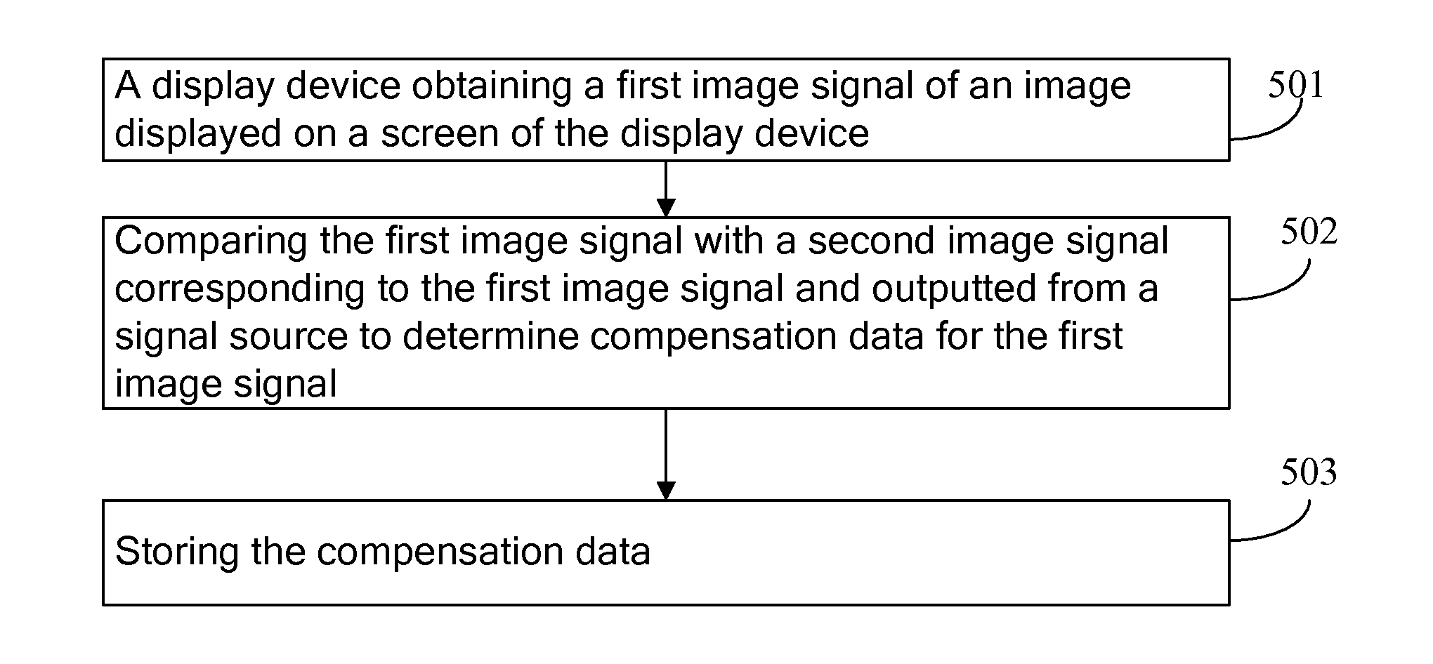
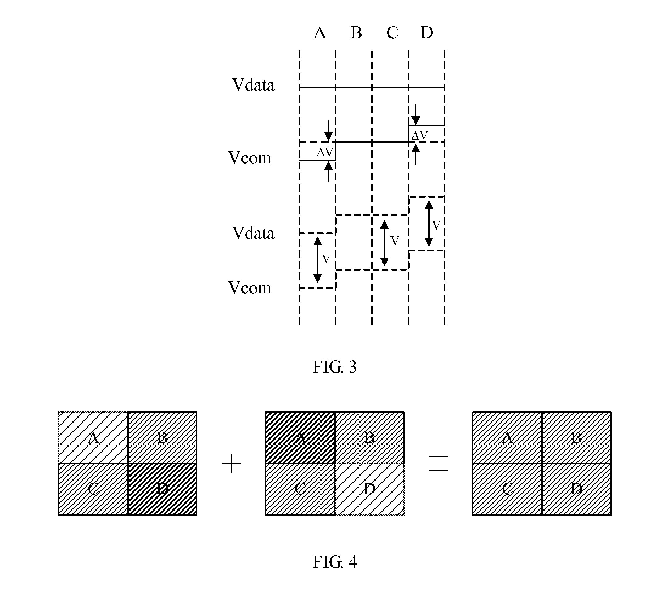
The invention provides a method and display device for uniform image display without changing the structure of the display device. The method compensates image signals based on data to ensure voltage differences between input signals and common electrodes are balanced, resulting in a more uniform display and improved user experience. This does not increase the cost and can be achieved without changing the existing full in-cell display device structure.

Problems solved by technology

However, the full in-cell technology integrates touch electrodes into common electrodes of an array substrate, the structure inevitably is more complex with respect to a mere display panel, the number of wires connected to a same electrode relatively is increased, but the space of the display screen is limited and the distribution space of signal wires also is limited, so that in the limited space, lengths of wires connected to pixel electrodes and common electrodes of the array substrate are not equal, and finally voltages applied on liquid crystal pixels are not equal, the displayed image is non-uniform as a result.
But the above-described method not only requires improving the array substrate manufacturing process itself but also requires adding additional transistors, so that the structure of the full in-cell display device is more complex and the transistor cost is increased.

Method used


Image

  • Method and dislay device for uniform image display
  • Method and dislay device for uniform image display
  • Method and dislay device for uniform image display

Examples


Embodiment Construction

[0031]In the following, with reference to accompanying drawings of embodiments of the invention, technical solutions in the embodiments of the invention will be clearly and completely described. Apparently, the embodiments of the invention described below only are a part of embodiments of the invention, but not all embodiments. Based on the described embodiments of the invention, all other embodiments obtained by ordinary skill in the art without creative effort belong to the scope of protection of the invention.

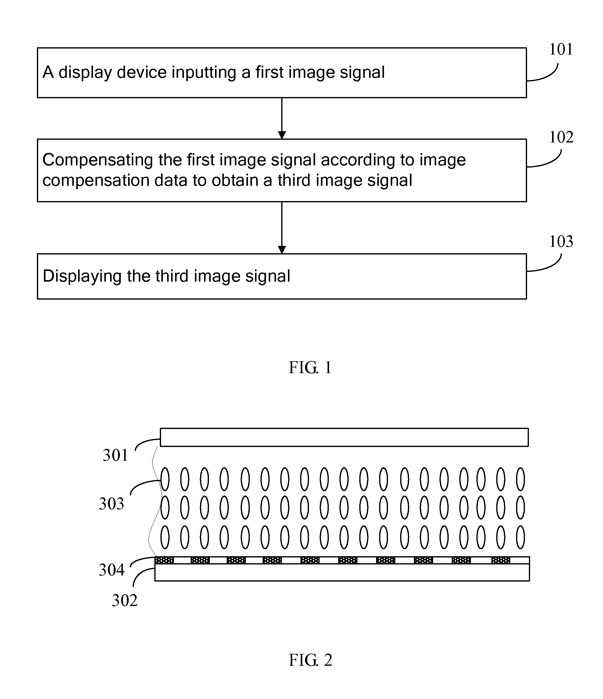
[0032]Referring to FIG. 1, which is a flowchart of an embodiment of a method for uniform image display of the invention. The method for uniform image display is adapted for being applied to a full in-cell display device, and in other embodiment it may be applied to other type display device and thus is not limited herein. The method in this embodiment includes following steps that:

[0033]101: the display device inputting a first image signal.

[0034]When the display device disp...


PUM


Abstract

A method and a display device for uniform image display are provided. The method is used for a full in-cell display device and includes steps of: a display device inputting a first image signal, compensating the first image signal according to image compensation data to obtain a third image signal and displaying the third image signal. The display device includes a color filter substrate, an array substrate and a liquid crystal layer disposed therebetween. A side of the array substrate facing toward the liquid crystal layer is disposed touch electrodes. The touch electrodes are combined with common electrodes of the array substrate and arranged on the array substrate in a matrix. The compensation data are common electrode voltage offsets determined according to differences between grayscale information of the first image signal and an original second image signal. Accordingly, the invention can effectively improve the displayed image uniformity.

Description

TECHNICAL FIELD[0001]The invention relates to the field of display technology, and particularly to a method and a display device for uniform image display.DESCRIPTION OF RELATED ART[0002]A touch screen, also known as touch panel, is an inductive type liquid crystal display device which can receive an input signal triggered by a touch object such as finger. When a graphic button on a screen is touched, a haptic feedback system on the screen can determine an occurred position of the touch operation based on a preset driving scan mode and then determine the clicked graphic button as well as the type of instruction. Compared with the traditional mechanical press-button panel, the touch screen is more convenient and therefore has been widely used.[0003]A projected capacitive touch screen is one of commonly used touch screens and also is a touch technology of using a capacitance change generated when a finger approaches a capacitive touch panel. Such touch technology is classified into se...

Claims


Application Information

Patent Timeline
Patent Type & Authority Applications(United States)
IPC IPC(8): G09G3/36G06F3/041G06F3/044
CPCG09G3/3655G06F3/044G06F3/0412G09G2300/0426G06F3/0416G09G2300/0408G09G2320/0233G09G3/3607G02F1/13338G06F3/147G09G3/36G09G3/3611G09G2354/00G09G2320/0285G06F3/04166G02F1/1362G06F3/041
Inventor LI, MANJI, FEILINTAN, XIAOPING
Owner SHENZHEN CHINA STAR OPTOELECTRONICS TECH CO LTD
Learn More