
Air conditioner for vehicle

a technology for air conditioners and vehicles, applied in the field of air conditioners, can solve the problems of limited power saving, and achieve the effect of reducing the power required to suppress fog on the window glass

Active Publication Date: 2016-11-24
DENSO CORP
View PDF6 Cites 79 Cited by
  • Summary
  • Abstract
  • Description
  • Claims
  • Application Information

AI Technical Summary

Benefits of technology

The present invention relates to a system for reducing power needed to suppress fog on a window glass in a vehicle. The technical effect of the invention is achieved through a second dehumidification mode that allows the coolant cooled by the outside air to circulate through an air-cooling heat exchanger, thereby dehumidifying the ventilation air to be blown into the vehicle interior. This mode reduces power required to suppress fog on the window glass compared to a first dehumidification mode where the coolant cooled by the low-pressure side refrigerant is circulated through the air-cooling heat exchanger. The second dehumidification mode is more efficient in dehumidifying the air when the outside-air temperature is low.

Problems solved by technology

However, based on studies undertaken by the inventors of the present application, in the related art disclosed in Patent Document 1, the compressor must be operated when a window glass is actually fogged, even though the frequency of operating the compressor for suppressing fog on the window glass can be decreased, which means the power saving is limited.

Method used


Image

  • Air conditioner for vehicle
  • Air conditioner for vehicle
  • Air conditioner for vehicle

Examples


first embodiment

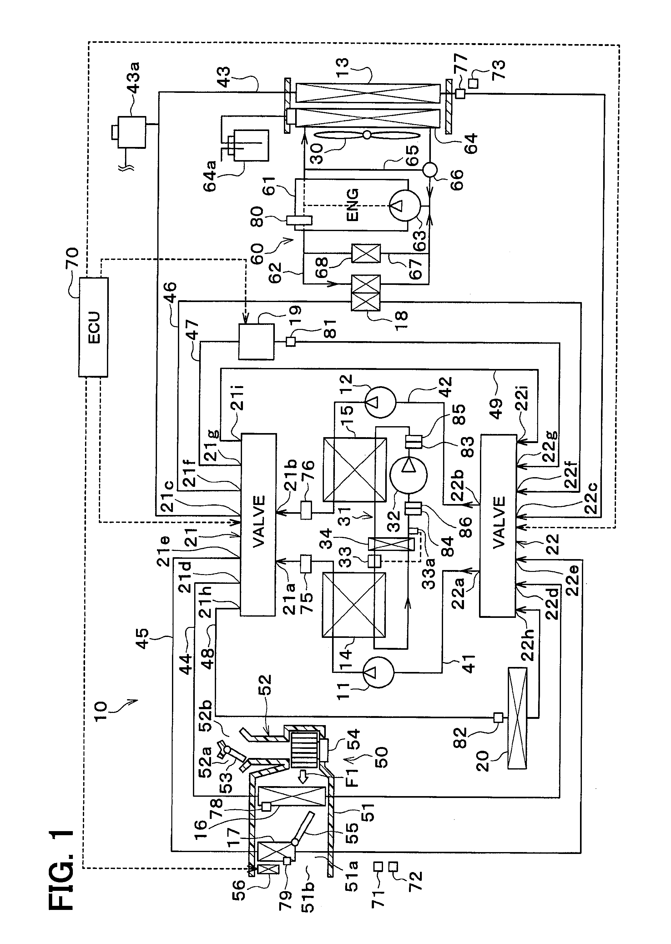
[0033]A thermal management system 10 for a vehicle shown in FIG. 1 is used to adjust various devices mounted on a vehicle or an interior of the vehicle to an appropriate temperature. In this embodiment, the vehicle thermal management system 10 is applied to a hybrid vehicle that can obtain the driving force for traveling of a vehicle from both an engine (internal combustion engine) and an electric motor for traveling (motor generator).

[0034]The hybrid car of this embodiment is configured as a plug-in hybrid car that can charge the battery (vehicle-mounted battery) mounted on the vehicle, with power supplied from an external power source (commercial power source) during stopping of the vehicle. For example, a lithium ion battery can be used as the battery.

[0035]The driving force output from the engine is used not only as a driving force for traveling of the vehicle, but also as a force for operating a generator. Power generated by the generator and power supplied from an external pow...

second embodiment

[0295]In this embodiment, as shown in FIG. 7, steps S181 and S184 in the flowchart of FIG. 6 of the first embodiment are changed to steps S181′ and S184′.

[0296]In step S181′, it is determined whether the temperature of the outside air increases or not. When the outside-air temperature is determined not to increase, the operation proceeds to step S182, whereas when the outside-air temperature is determined to increase, the operation proceeds to step S183.

[0297]In step S184′, it is determined whether the surface temperature TC of the cooler core 16 exceeds the target temperature TCO or not. When the surface temperature TC of the cooler core 16 is determined to exceed the target temperature TCO, it is determined that the window fogging cannot be prevented in the compressor-off mode. Then, the operation proceeds to step S185, in which the thermal management system is transferred to the compressor-on mode.

[0298]As mentioned above, in this embodiment, in the compressor-off mode (second de...

third embodiment

[0304]Although in the first embodiment, the thermal management system can be switched between a state of connection of the radiator 13 to the low-temperature side coolant circuit and a state of connection thereof to the high-temperature side coolant circuit, in this embodiment, the radiator 13 is constantly connected to the low-temperature side coolant circuit as shown in FIG. 8.

[0305]The refrigeration cycle 31 is provided with a condenser 15A that condenses a high-pressure side refrigerant by exchanging heat between the high-pressure side refrigerant discharged from the compressor 32 and the outside air.

[0306]Although not shown, the heater core 17 is adapted to allow the coolant (engine coolant) for the engine cooling circuit 60 to circulate through the heater core 17. The heater core 17 may allow for circulate of hot water (heat medium) heated with the high-pressure side refrigerant in the refrigeration cycle 31 therethrough. An electric heater (for example, a PTC heater) may be d...


PUM


Abstract

An air conditioner for a vehicle includes a pump that draws and discharges a heat medium, a cooler core that exchanges sensible heat between the heat medium and ventilation air into a vehicle interior to cool and dehumidify the ventilation air, a heat-medium and outside-air heat exchanger that exchanges sensible heat between the heat medium and outside air, a compressor adapted to draw and discharge a refrigerant in a refrigeration cycle, a heat-medium cooling heat exchanger that cools the heat medium by exchanging heat between a low-pressure side refrigerant in the refrigeration cycle and the heat medium, and first and second switching valves that switch between a first dehumidification mode for circulation of the heat medium between the cooler core and the heat-medium cooling heat exchanger and a second dehumidification mode for circulation of the heat medium between the cooler core and the heat-medium and outside-air heat exchanger.

Description

CROSS REFERENCE TO RELATED APPLICATION[0001]This application is based on Japanese Patent Applications No. 2014-014099 filed on Jan. 29, 2014, and No. 2014-262643 filed on Dec. 25, 2014, the contents of which are incorporated herein by reference in its entirety.FIELD OF THE INVENTION[0002]The present disclosure relates to air conditioners for use in vehicles.BACKGROUND ART[0003]A conventional air conditioner for a vehicle includes an evaporator that cools and dehumidifies ventilation air to be blown into a vehicle interior by exchanging heat between a low-pressure side refrigerant in a refrigeration cycle and the ventilation air within the vehicle interior. When intended to suppress fog on a window glass using an inside-air circulation mode of air-conditioning by circulating the inside air without introducing the outside air into the vehicle interior, a compressor in the refrigeration cycle is operated, causing the evaporator to dehumidify the ventilation air in the vehicle interior....

Claims


Application Information

Patent Timeline
IPC IPC(8): B60H1/32B60H1/00
CPCB60H1/3207B60H1/323B60H1/00428B60H1/004B60H1/00864B60H2001/3291B60H2001/00957B60H2001/3245B60H2001/3255B60H2001/3266B60H1/00785F25B25/005F25B29/003F25B2339/047F25B2700/1931F25B2700/1933F25B2700/21151F25B2700/21152B60H1/00899B60H2001/00928B60H1/00278B60H2001/00307B60H1/32281B60H1/32284
Inventor ENOMOTO, NORIHIKOKAKEHASHI, NOBUHARUOMI, YASUMITSUMAKIHARA, MASAMICHIKISHITA, HIROSHI
Owner DENSO CORP
Learn More