
Fuse having an explosion chamber

a technology of fuse and explosion chamber, which is applied in the field of fuse, can solve the problems of arc between the two separated parts, complex, and failure of the isolating device to suppress the developing arc, and achieve the effect of simple, reliable and cost-effectiv

Active Publication Date: 2016-11-17
LISA DRAXLMAIER GMBH
View PDF24 Cites 14 Cited by
  • Summary
  • Abstract
  • Description
  • Claims
  • Application Information

AI Technical Summary

Benefits of technology

The present invention provides an easy and efficient way to stop an electrical arc from developing between isolated parts of a current conductor in a fuse, or to put out an arc that’s already there. This can be useful for high-voltage fuses.

Problems solved by technology

At high voltages, the problem arises that, after a power lead has been cut, an arc may occur between the two separated parts.
The arc can be extinguished by adding a fluid acting in an electrically insulating manner, such as an oil, a gel or a gas; this, however, is very complex.
This safety device, however, includes a variety of drawbacks.
For example, the safety device does not suppress a developing arc.
The isolating device also fails to suppress a developing arc.
Under the impact of the explosion, the separated parts are reliably deformed into the isolating chamber on different sides of the partition, which may bring about a suppression of an arc.
If the current conductor were to impinge on the partition prior to being separated, this could possibly impede, or even completely prevent, the deformation thereof, and thus the separation.

Method used


Image

  • Fuse having an explosion chamber
  • Fuse having an explosion chamber
  • Fuse having an explosion chamber

Examples


Embodiment Construction

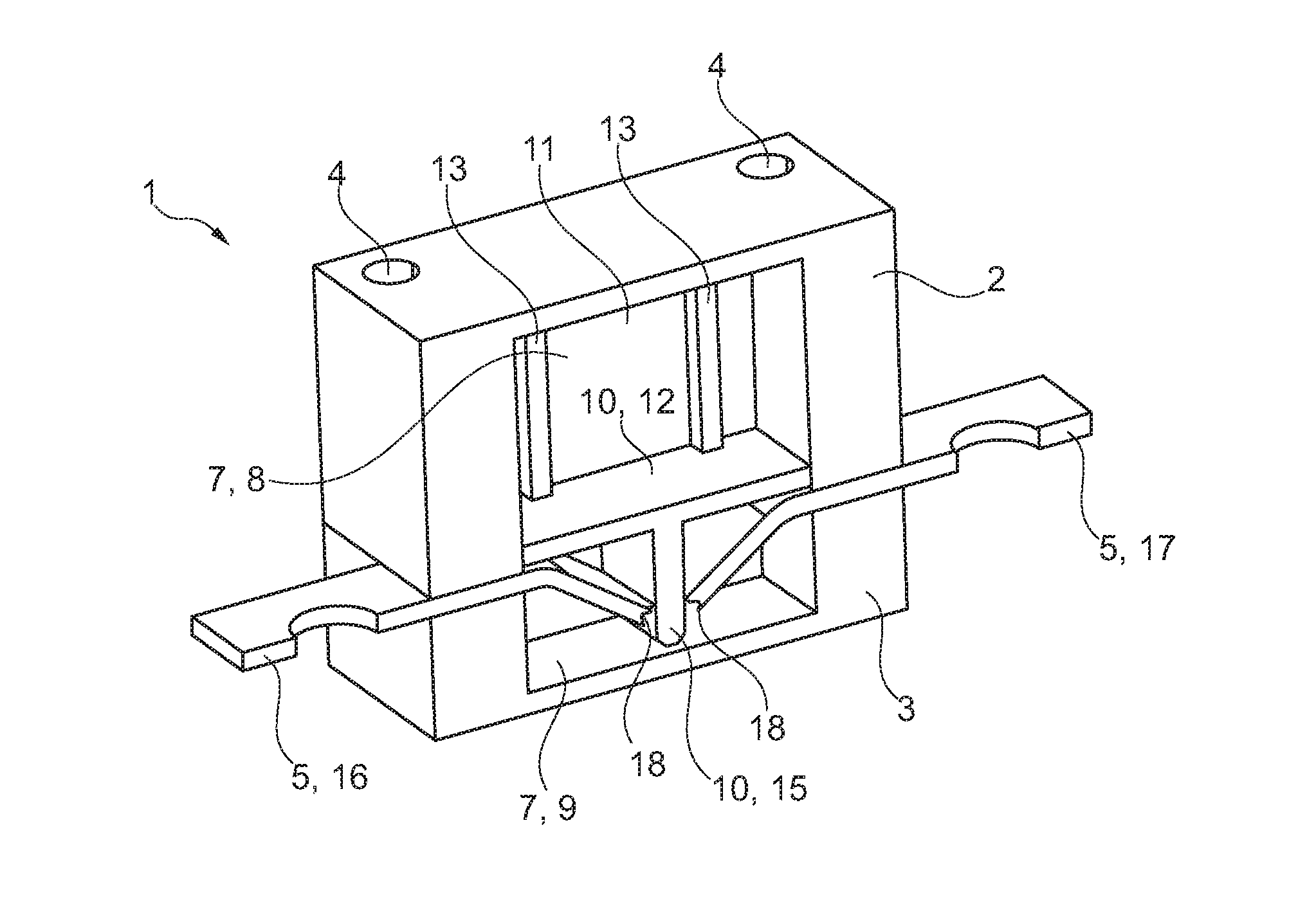
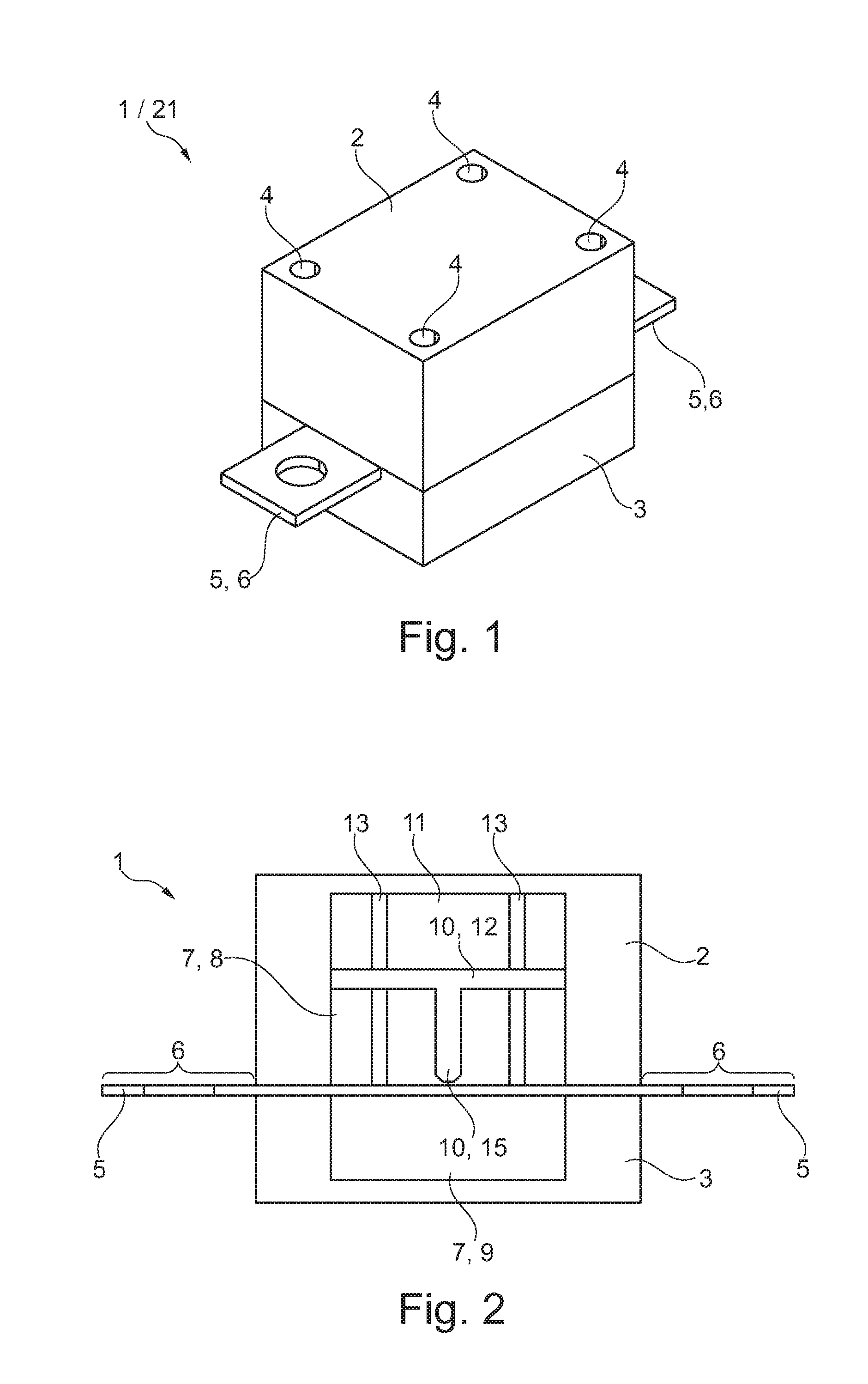
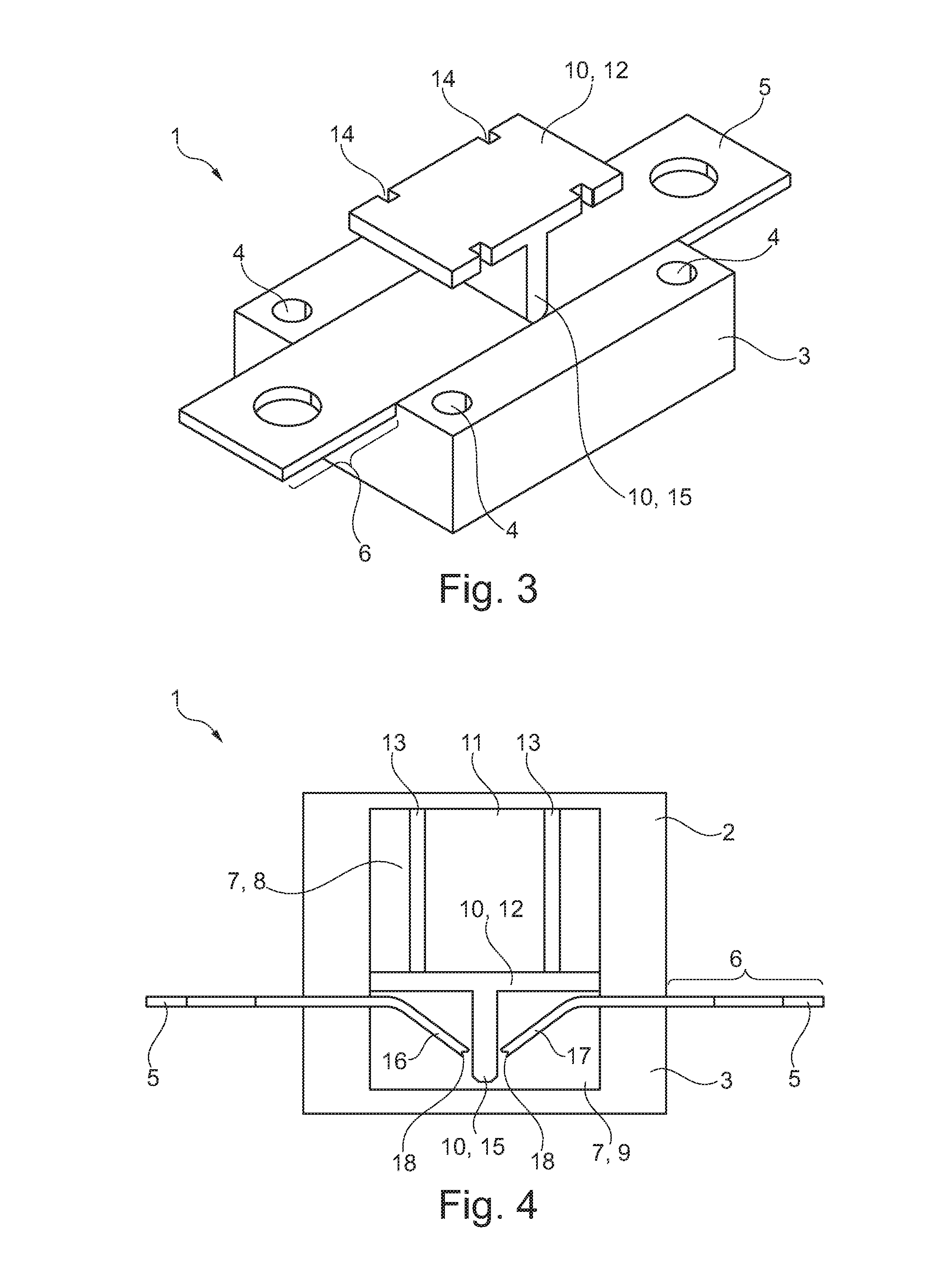
[0043]FIG. 1 shows an oblique view of an exemplary pyrotechnic fuse 1 comprising a first “top” housing part 2 and a second “bottom” housing part 3. The two housing parts 2 and 3 have aligned boreholes 4 through which the two housing parts 2 and 3 can be fixedly connected, for example screwed, to each other. The housing 2, 3 assembled from the two housing parts 2 and 3 can be made of electrically insulating plastic material, for example. End regions of a power lead protrude from the housing 2, 3 in the form of a metallic conductor rail 5 as electrical connections 6.

[0044]The fuse 1 can protect a current flow at an isolating current of at least 7500 A at 450 volts direct current (VDC) to 1500 volts direct current without effect on the surrounding area. The fuse 1 may be a high-voltage fuse or a “high-voltage pyrofuse.”

[0045]The housing 2, 3 can have a cuboid basic shape. An extinguishing magnet (not shown), if present, can be recessed in the housing 2, 3.

[0046]As is shown in FIG. 2, t...


PUM


Abstract

Embodiments disclose a fuse comprising a one power lead, an explosion chamber and an isolating chamber, wherein the fuse is designed such that a power lead can be broken into at least two parts by an explosion triggered in an explosion chamber. The two parts are separated from each other in an associated isolating chamber by a respective electrically insulating partition. Embodiments disclose a method comprising a power lead, an explosion chamber and an isolating chamber, wherein an explosion is triggered in the explosion chamber so that the power lead is broken into at least two parts and bent into the isolating chamber such that at least two parts are separated from one another by an electrically insulating partition. The present disclosure can be applied to pyrotechnic fuses for vehicles and to high-voltage fuses.

Description

CROSS REFERENCE TO RELATED APPLICATION[0001]This application is based upon and claims the benefit of prior German Patent Application No. 10 2015 107 579.2, filed on May 13, 2015, the entire contents of which are incorporated herein by reference.TECHNICAL FIELD[0002]The present disclosure relates to a fuse, comprising at least one power lead and at least one explosion chamber, wherein the fuse is designed such that the at least one power lead can be separated into at least two parts when an explosion is triggered in at least one explosion chamber. The present disclosure also relates to a method for operating a fuse comprising at least one power lead and one explosion chamber, wherein an explosion is triggered in the explosion chamber so that the at least one power lead is separated into at least two parts. The present disclosure can be applied to pyrotechnic fuses for vehicles, in particular motor vehicles. The present disclosure can also be applied to high-voltage fuses.BACKGROUND O...

Claims


Application Information

Patent Timeline
Patent Type & Authority Applications(United States)
IPC IPC(8): H01H39/00H01H33/18
CPCH01H33/182H01H39/006H01H9/34H01H9/443
Inventor FELLMER, MARKOGRUBER, CHRISTIANFALTERMEIER, PETER
Owner LISA DRAXLMAIER GMBH
Learn More