Bump detection and effect reduction in autonomous systems

Active Publication Date: 2016-11-17
AUTONOMOUS SOLUTIONS +1
View PDF6 Cites 34 Cited by
  • Summary
  • Abstract
  • Description
  • Claims
  • Application Information

AI Technical Summary

Benefits of technology

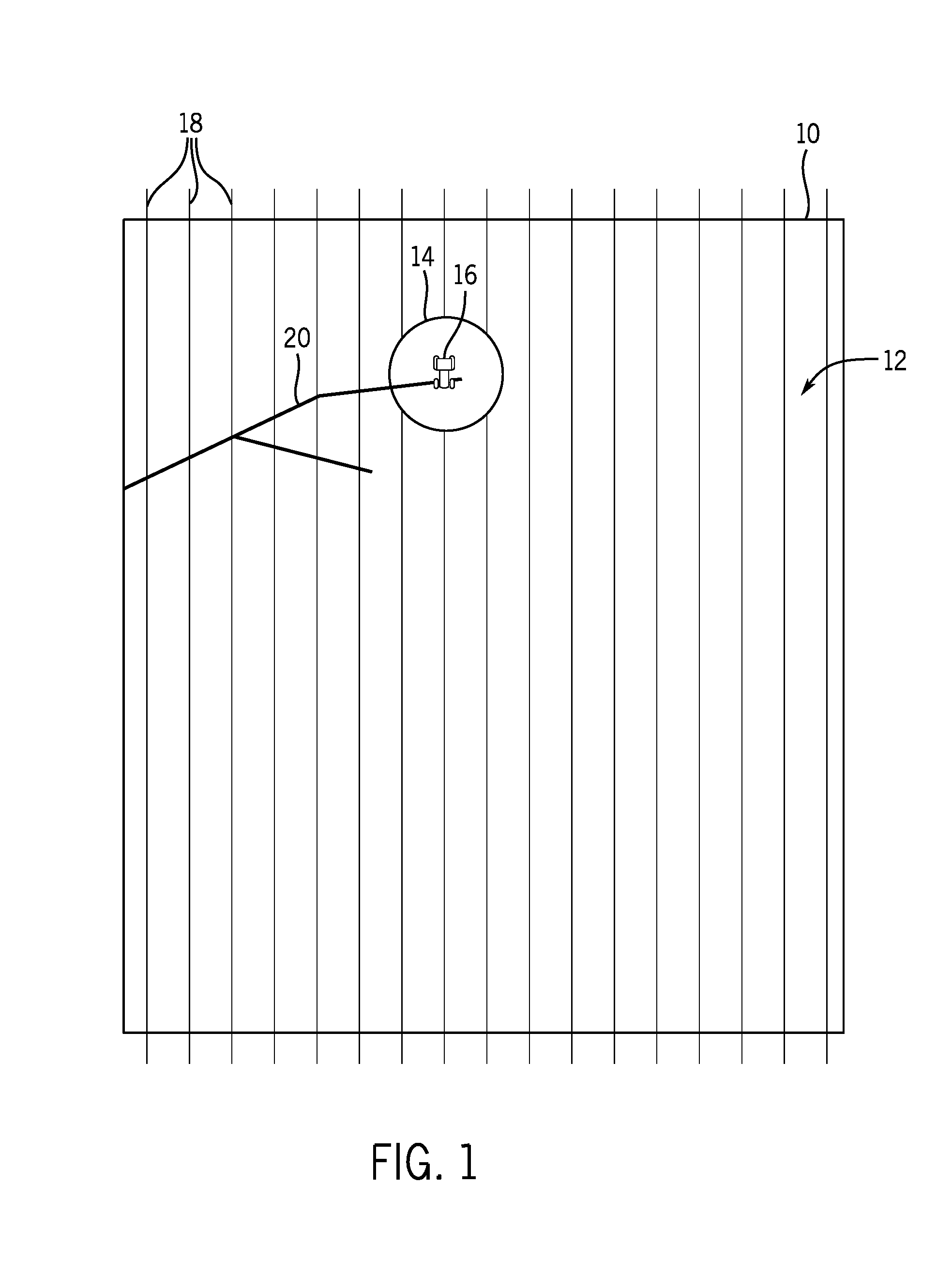
The present patent is about a control system for an agricultural vehicle that can automatically adjust its speed and steering to avoid bumps in the terrain. The system uses sensors on the vehicle to detect bumps and sends signals to a base station to map the terrain and identify areas with bumps. The base station then sends signals to the agricultural vehicle to adjust its speed and steering to avoid the bumps. This system can improve the efficiency and safety of agricultural vehicles by automatically avoiding bumps and reducing the likelihood of accidents.

Problems solved by technology

Some terrains (e.g., fields) may develop ruts from runoff water over time.
In particular, it is not uncommon for ruts to form on fields located on the side of a hill due to drainage.
Additionally, there may be other obstacles (e.g., rocks) and / or adverse conditions (e.g., soft soil) present in some fields.
These ruts, obstacles, and / or adverse conditions may be difficult to detect with sensors due to crops growing above and covering the ruts, obstacles, and / or adverse conditions.
As such, base stations controlling autonomous agricultural vehicles working the fields may not have knowledge of the existence of the ruts, obstacles, and / or adverse conditions and may instruct the autonomous agricultural vehicle to drive at normal operating velocities through them.
In some instances, driving the autonomous agricultural vehicle through the ruts, obstacles, and / or adverse conditions may lead to undesired conditions of the vehicle and / or a loss of control of the vehicle.

Method used


Image

  • Bump detection and effect reduction in autonomous systems
  • Bump detection and effect reduction in autonomous systems
  • Bump detection and effect reduction in autonomous systems

Examples


Embodiment Construction

[0017]One or more specific embodiments of the present disclosure will be described below. In an effort to provide a concise description of these embodiments, all features of an actual implementation may not be described in the specification. It should be appreciated that in the development of any such actual implementation, as in any engineering or design project, numerous implementation-specific decisions must be made to achieve the developers' specific goals, such as compliance with system-related and business-related constraints, which may vary from one implementation to another. Moreover, it should be appreciated that such a development effort might be complex and time consuming, but would nevertheless be a routine undertaking of design, fabrication, and manufacture for those of ordinary skill having the benefit of this disclosure.

[0018]When introducing elements of various embodiments of the present disclosure, the articles “a,”“an,”“the,” and “said” are intended to mean that th...


PUM


Abstract

In one embodiment, a control system for a base station includes a first transceiver configured to receive a first signal and send a second signal to an agricultural vehicle. The first signal indicates at least an acceleration of the vehicle, a current velocity of the vehicle, and a location relative to a terrain where the vehicle experienced the acceleration, and the second signal indicates a vehicle target velocity. The control system includes a controller configured to determine a bump severity value based on the acceleration and the current velocity of the vehicle, mark an area indicative of the bump on a map of the terrain when the bump severity value exceeds a threshold, and automatically generate the second signal when the vehicle enters the area. The target velocity is based on a proximity of the vehicle to the bump, the bump severity value, or some combination thereof.

Description

CROSS REFERENCE TO RELATED APPLICATIONS[0001]This application claims priority from and the benefit of U.S. Provisional Patent Application No. 62 / 160,366, entitled “BUMP DETECTION AND EFFECT REDUCTION IN AUTONOMOUS SYSTEMS,” filed May 12, 2015, which is hereby incorporated by reference in its entirety.BACKGROUND[0002]The present application relates generally to autonomous agricultural systems, and more specifically, to systems and methods for detecting bumps and reducing their effects on autonomous agricultural vehicles.[0003]Some terrains (e.g., fields) may develop ruts from runoff water over time. In particular, it is not uncommon for ruts to form on fields located on the side of a hill due to drainage. Additionally, there may be other obstacles (e.g., rocks) and / or adverse conditions (e.g., soft soil) present in some fields. These ruts, obstacles, and / or adverse conditions may be difficult to detect with sensors due to crops growing above and covering the ruts, obstacles, and / or a...

Claims


Application Information

Patent Timeline
IPC IPC(8): G05D1/02A01B76/00G05D1/00
CPCG05D1/0223A01B76/00G05D1/0011B60K31/0008B60K31/0058G05D1/0274A01B69/008B60W30/02
Inventor FOSTER, CHRISTOPHER A.DEBILDE, BENOITMORWOOD, DANIEL JOHNHORNBERGER, MICHAEL G.TURPIN, BRET TODD
Owner AUTONOMOUS SOLUTIONS
Why Eureka
Try Eureka