
Motor drive for linear machines with distributed windings

a technology of distributed windings and motor drives, which is applied in transportation and packaging, mine lifts, elevators, etc., can solve the problems of increasing the likelihood of position signal latency and complicating vehicle propulsion

Active Publication Date: 2016-10-27
OTIS ELEVATOR CO
View PDF0 Cites 6 Cited by
  • Summary
  • Abstract
  • Description
  • Claims
  • Application Information

AI Technical Summary

Benefits of technology

The patent describes a linear propulsion system that uses a track, a vehicle, and a mover functionally mounted on the vehicle. The mover includes a plurality of magnets and a dual inverter system with two multi-phase inverters and shared input hardware. The system generates a propulsion force when the mover is activated and deactivated. The technical effects of the patent include improved efficiency and control of the linear propulsion system, as well as reduced wear and tear on the vehicle and track. The patent also describes an elevator system that uses the same technology.

Problems solved by technology

Such a design may increase the likelihood of position signal latency complicating propulsion of the vehicle during the transition from one inverter to another.

Method used


Image

  • Motor drive for linear machines with distributed windings
  • Motor drive for linear machines with distributed windings
  • Motor drive for linear machines with distributed windings

Examples


Embodiment Construction

[0026]The linear propulsion system 10 disclosed herein may be utilized in applications that require movement of a vehicle along a track. For example, the linear propulsion system may be utilized for elevators, trains, roller coasters, or the like.

[0027]To facilitate the understanding of this disclosure, the linear propulsion system will be described as utilized in a linear motor propelled elevator system. It is to be understood that the linear propulsion system is not intended to be limited to elevator applications. The elevator application described herein is an exemplary embodiment described in order to facilitate understanding of the disclosed propulsion system.

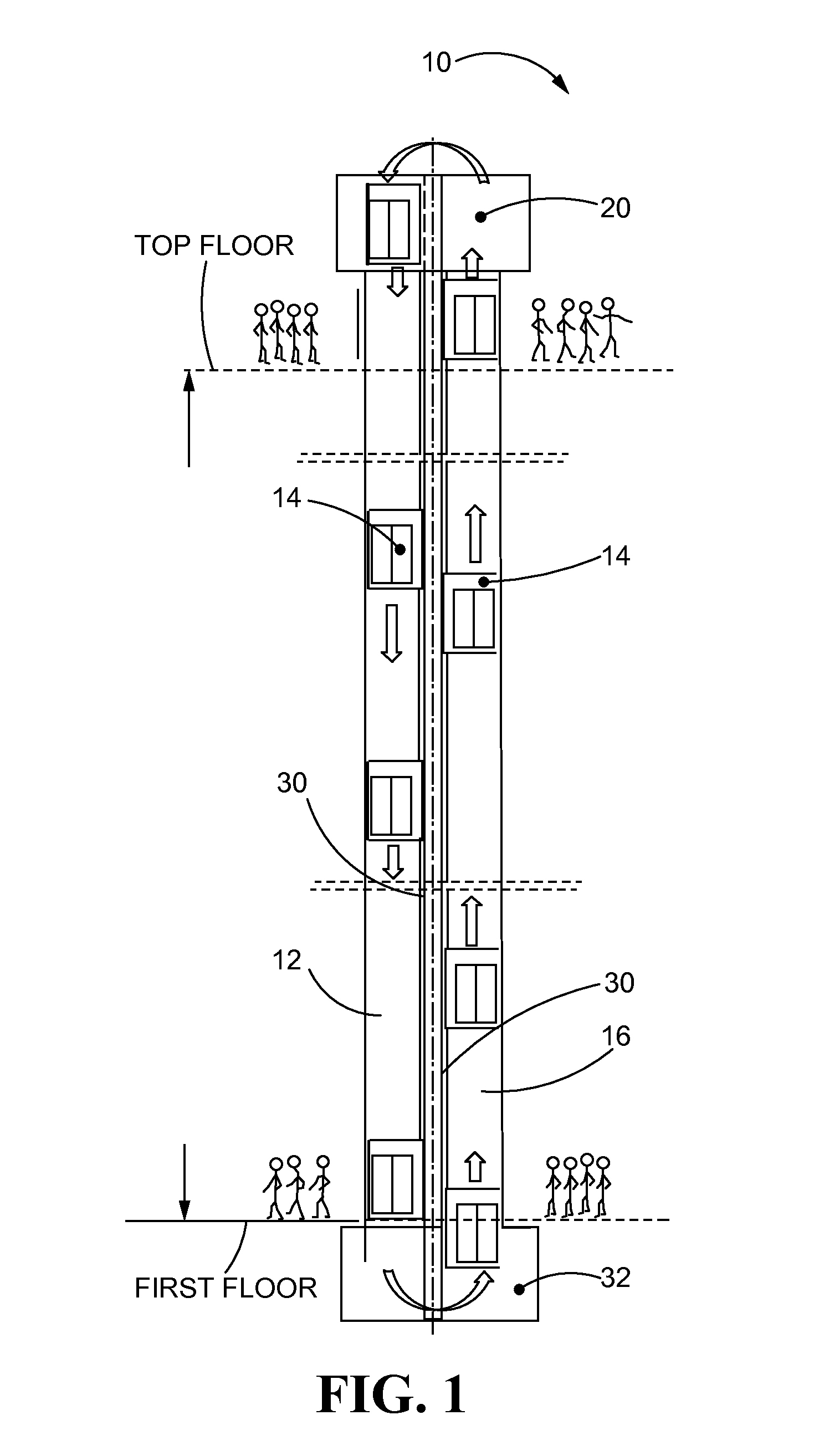
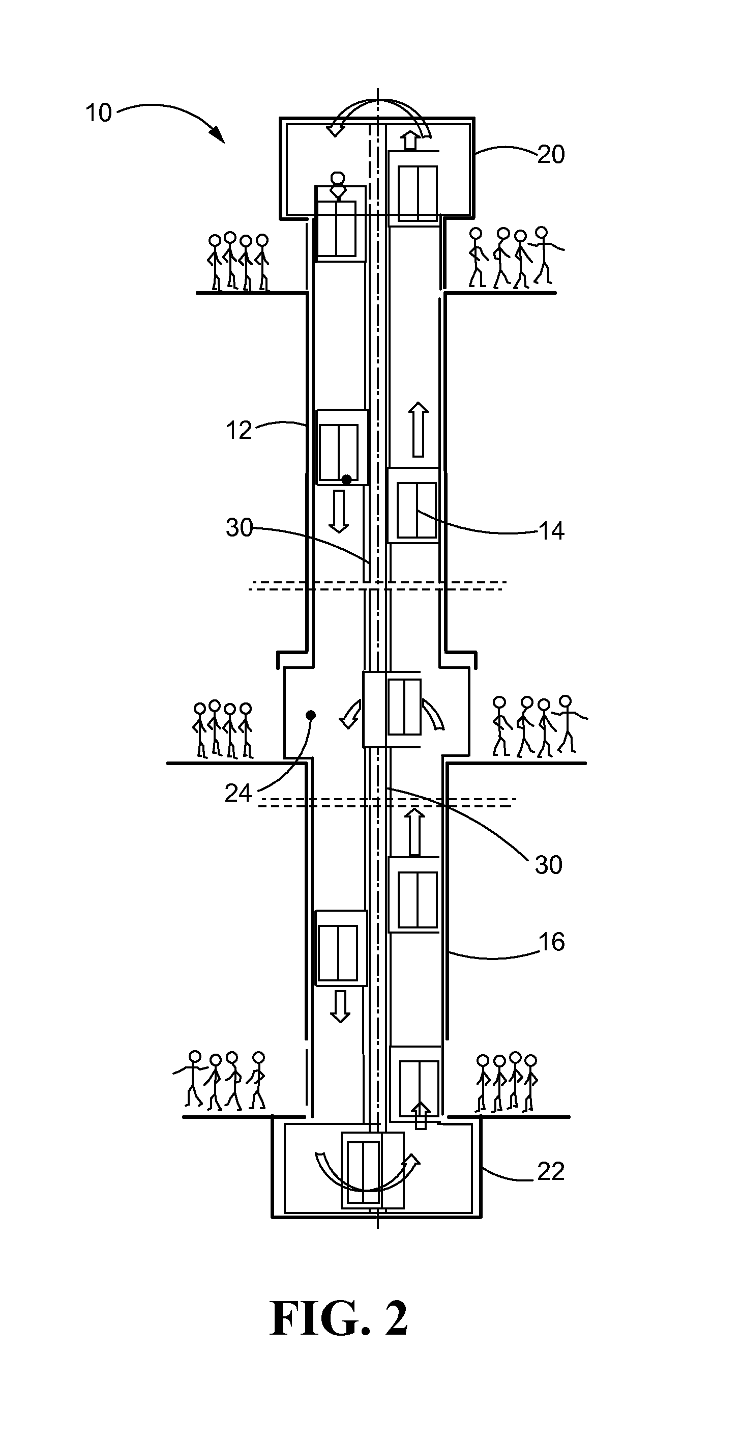
[0028]Referring now to FIG. 1, a propulsion system 10 is shown in schematic fashion. The propulsion system is an exemplary elevator system that utilizes one or more linear motors. As shown in FIG. 1, the elevator system 10 includes a first hoistway 12 provided vertically within a multi-story building. Elevator cars 14 may ...


PUM


Abstract

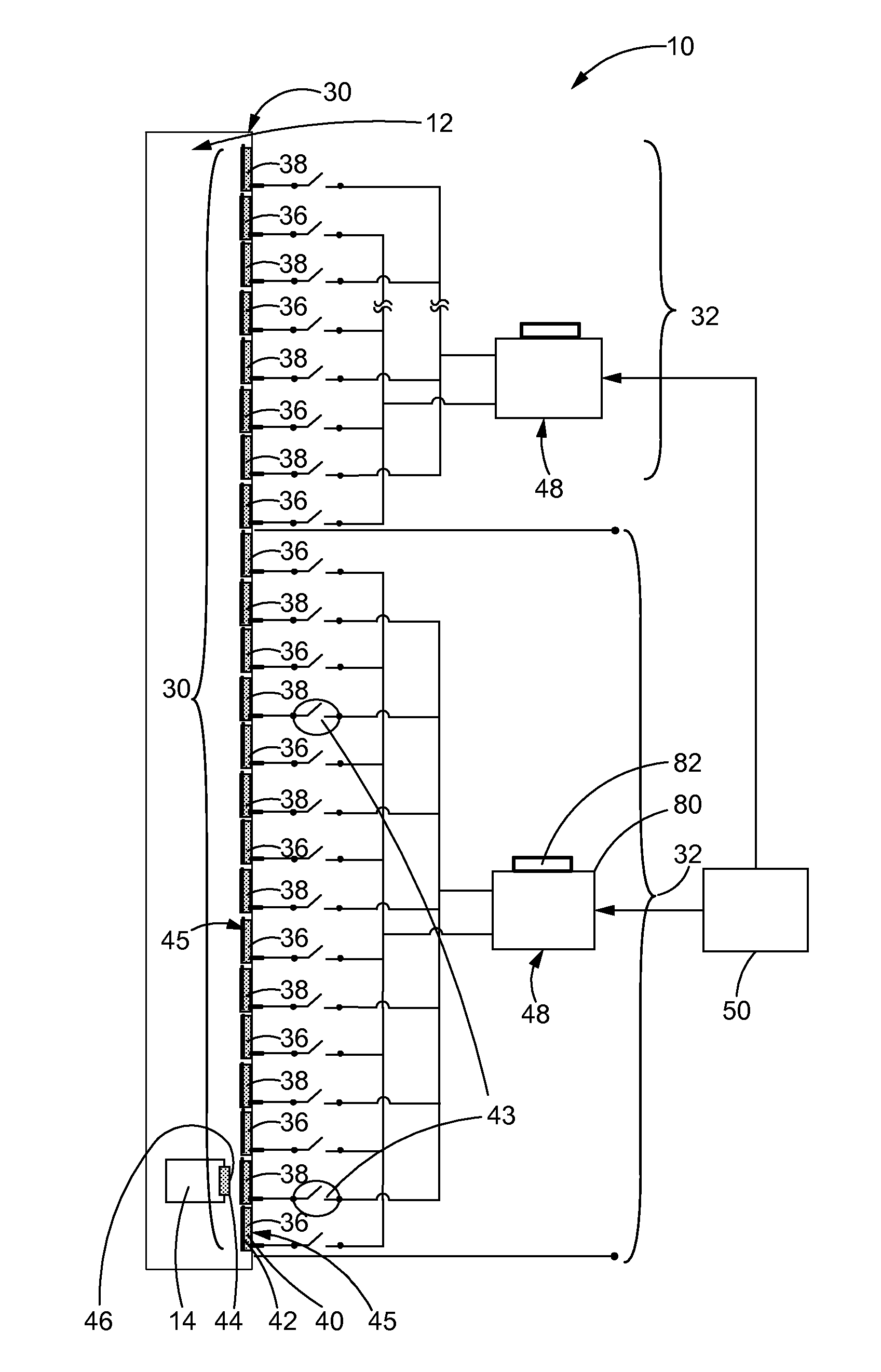
A linear propulsion system (10) and method of assembling and testing the same is disclosed. The linear propulsion system (10) may comprise a track (30), a vehicle (14), a mover (44) mounted to the vehicle (14), and a dual inverter system (48). The track (30) may comprise a first plurality (36) of stator sections (45) interleaved with a second plurality (38) of stator sections (45). The dual inverter system (48) may include first and second multi-phase inverters (52a, 52b) that share input hardware (54).

Description

[0001]FIELD OF THE DISCLOSURE[0002]The present disclosure generally relates to drive systems, and, in particular, relates to drive systems utilized with linear machines with distributed windings.BACKGROUND OF THE DISCLOSURE[0003]Linear propulsion electric machines may be used to propel vehicles or the like in a wide variety of applications. In general, linear propulsion of vehicles may be achieved with a linear electric machine whose stator spans the length of the path or track that the vehicle travels. In such applications, the mover is typically mounted on the vehicle. The stator interacts with the mover mounted on the vehicle to propel the vehicle along the track. The stator may include of a series of coils which line the track. One way of powering those coils is by machine power-electronic inverters.[0004]“Japan's superconducting Maglev train,” Instrumentation & Measurement Magazine, IEEE , vol.5, no.1, pp.9-15, Mar 2002, authored by M. Ono, S. Koga and H. Ohtsuki, H. describes ...

Claims


Application Information

Patent Timeline
Patent Type & Authority Applications(United States)
IPC IPC(8): B66B11/04B66B19/00B66B1/30
CPCB66B11/0407B66B9/003B66B19/00B66B1/30B66B9/02
Inventor RODRIGUEZ, FERNANDO
Owner OTIS ELEVATOR CO
Learn More