Protective cap for a dispenser and dispenser for discharging pharmaceutical and/or cosmetic liquids

a technology for protecting caps and dispensers, applied in the direction of caps, liquid handling, applications, etc., can solve the problems of inability to discharge channels, etc., and achieve the effect of facilitating user handling and efficiently filtering ou

Active Publication Date: 2016-10-27
APTAR RADOLFZELL
View PDF4 Cites 9 Cited by
  • Summary
  • Abstract
  • Description
  • Claims
  • Application Information

AI Technical Summary

Benefits of technology

[0020]As an alternative, or in addition, to shrink-fitting, the film wrapper, in advantageous configurations, is welded to the protective cap. The weld seam ensures air tightness and germ proofing. A weld seam here is arranged separately from a ventilation opening. This means that any residues which may possibly remain on the protective cap once the film wrapper has been torn off do not present a hazard.
[0021]In yet another configuration, the sealing element is designed in the form of a pull-off lug which is injection molded on the protective cap. The pull-off lug here can be produced along with the protective cap in the form of an integral constituent part of the same. It is thus possible to dispense with additional assembly steps or other production steps. In one configuration, the pull-off lug is coupled to a tamperproof seal, and this results in particularly straightforward handling for a user.
[0022]Following removal of the sealing element, the at least one ventilation opening provides for rapid drying. In order to alleviate the problem of germs being introduced via said ventilation opening, one configuration provides an antibacterial configuration of the surfaces, as is known from DE 10 2011 086 755 A1. Reference is made in full here to the contents of DE 10 2011 086 755 A1.
[0023]As an alternative, or in addition, an inner side of the protective cap has provided on it, in the region of the at least one ventilation opening, an absorber element, in particular an absorber element with filter properties, such as a microfiltration membrane or an ultrafiltration membrane. The absorber element assists in drying the dispenser by virtue of absorbing and distributing the residual droplet. In one configuration, the absorber element has filter properties in addition, in particular a microfiltration membrane or an ultrafiltration membrane is provided. This reduces the introduction of germs via the ventilation openings once the sealing element has been removed. A microfiltration membrane within the context of the application denotes a microporous membrane which has an average pore diameter or a cutoff of approximately 0.1 μm to approximately 0.3 μm, preferably approximately 0.2 μm. Bacteria have a size of approximately 0.2 to approximately 5 μm, and can therefore be filtered out efficiently by means of a microfiltration membrane. An ultrafiltration membrane within the context of the application denotes a microporous membrane which has an average pore diameter or a cutoff of approximately 10 nm. This means that viruses of a size of 15 nm can also be filtered out. The absorber element is configured, for example, in the form of a sponge-like element, woven fabric or membrane. In one configuration, the absorber element is made of a material from the group comprising polysulfone, polyethersulfone, cellulose, cellulose derivatives, polyvinylidene fluoride, polyamide, polyester and polyacrylonitrile and / or combinations thereof.

Problems solved by technology

As a result of the outlet valve, it is always the case that, following closure of the same, it is not possible for any liquid which has passed into a portion of the outlet channel on an outlet-valve side directed away from the liquid reservoir, or which has remained in the surroundings of the exit opening outside the outlet channel, to be sucked back into the dispenser.
However, it is possible for the ventilation openings, for their part, to cause contamination again.

Method used


Image

  • Protective cap for a dispenser and dispenser for discharging pharmaceutical and/or cosmetic liquids
  • Protective cap for a dispenser and dispenser for discharging pharmaceutical and/or cosmetic liquids
  • Protective cap for a dispenser and dispenser for discharging pharmaceutical and/or cosmetic liquids

Examples


Embodiment Construction

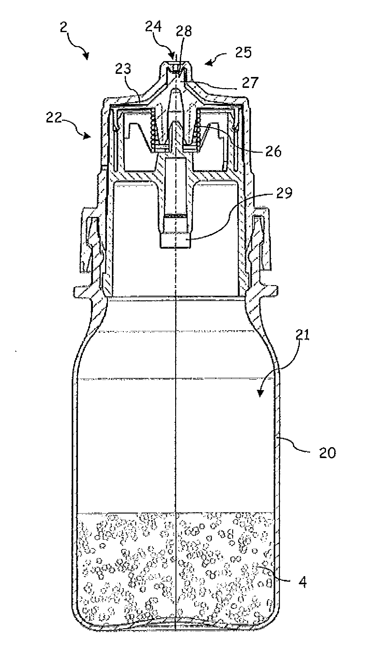
[0034]FIG. 1 shows, in the first instance, a dispenser 2 which is intended for discharging pharmaceutical and / or cosmetic liquids and is suitable, in particular, for unpreserved ophthalmic preparations.

[0035]Said dispenser 2 has a liquid reservoir 21, which is delimited by a container body 20. The liquid 4 is stored in the liquid reservoir 21. An outlet subassembly 22 has been placed in position, and fastened by means of a latching connection, on the container body 20. Said outlet subassembly 22 serves for directing liquid from the liquid reservoir 21 to an exit opening 24 through an outlet channel 23. The exit opening 24 illustrated is configured in the form of a droplet-forming surface and widens conically in the discharging direction.

[0036]On account of the section plane in FIG. 1, the latter illustrates merely a final part of the outlet channel 23. The outlet channel 23 has arranged in it an outlet valve 25 which, in a closed state, closes the outlet channel 23, and therefore li...


PUM

PropertyMeasurementUnit
pore diameteraaaaaaaaaa

Abstract

A protective cap for a dispenser for discharging pharmaceutical and/or cosmetic liquids, wherein the dispenser has a liquid reservoir and an outlet opening through which the liquid can be dispensed into a surrounding atmosphere, and wherein the protective cap has at least one ventilation opening to allow communication between an interior and external surroundings. An irreversibly removable sealing element which covers the at least one ventilation opening is arranged on the protective cap, which sealing element closes the at least one ventilation opening in an airtight and germproof manner before a first use.

Description

APPLICATION AREA AND PRIOR ART[0001]The invention relates to a protective cap for a dispenser and to a dispenser for discharging pharmaceutical and / or cosmetic liquids. Such a dispenser comprises a liquid reservoir and an exit opening, through which the liquid can be discharged into a surrounding atmosphere.[0002]A liquid stored in the liquid reservoir is fed in the direction of the exit opening in order to be discharged, it being possible for this to take place by way of a large number of different mechanisms. For example, the liquid reservoir may be designed in the form of a squeeze bottle, of which the contents can be subjected to pressure as a result of the walls being deformed. It is also possible to use a separate pumping device.[0003]Dispensers of the type in question are known from the prior art, for example from DE 10 2011 086 755 A1. The dispenser comprises an outlet channel and an outlet valve, which is arranged in the outlet channel and opens in a pressure-dependent mann...

Claims


Application Information

Patent Timeline
Patent Type & Authority Applications(United States)
IPC IPC(8): B65D51/16B65D41/32B65D51/18B65D47/20
CPCB65D51/1616B65D47/2068B65D2251/0087B65D51/18B65D2251/0015B65D41/32B65D41/48B65D2205/025B65D51/16
Inventor WOCHELE, MATTHIAS
Owner APTAR RADOLFZELL
Why Eureka
Try Eureka