
Shift register, gate driving circuit and display device

a technology of gate driving circuit and shift register, which is applied in the field of display technology, can solve the problems of high cost, unstable output of shift register, poor stability of etc., and achieve the effects of stable output, stable output of gate driving circuit, and reduced power consumption

Inactive Publication Date: 2016-10-20
BOE TECH GRP CO LTD
View PDF3 Cites 46 Cited by
  • Summary
  • Abstract
  • Description
  • Claims
  • Application Information

AI Technical Summary

Benefits of technology

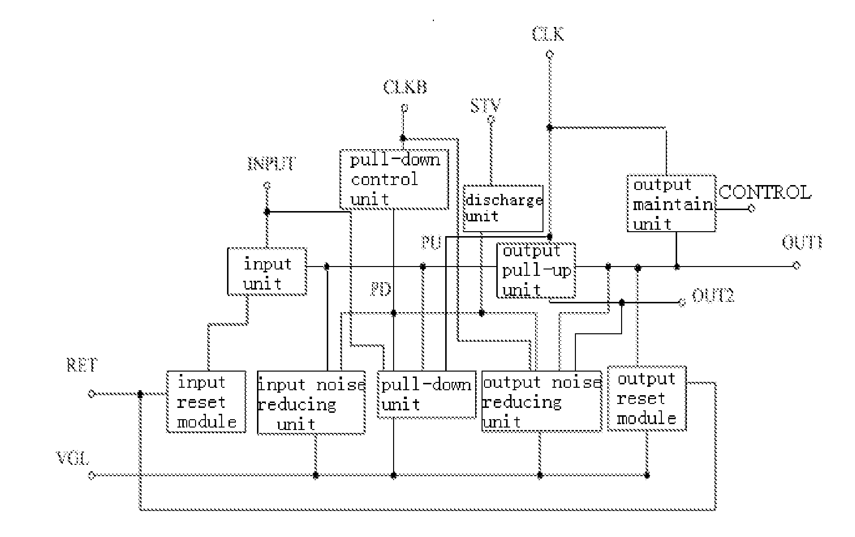
The technical effect of this patent is to provide a shifter register and gate driving circuit that have lower power consumption. The shift register includes an output noise reducing unit that reduces output noise at the first signal output terminal based on the pull-down control node and signal input from the second clock signal input terminal. The output maintaining unit maintains stability of output from the first signal input terminal in accordance with signals inputted from the control signal input terminal and the first clock signal input terminal to avoid poor stability of output from the gate driving circuit due to a long transition period between adjacent frames and reduces power consumption. The gate driving circuit of the present invention provides stable output and low power consumption.

Problems solved by technology

Currently, most of TFT-LCD devices are provided with a gate driving circuit and a source driving circuit on outer side of a display panel, resulting in a high cost.
Since there is a transition period between display of any two adjacent frames of picture, and during the transition period, each of the shift registers does not operate, output potentials of the shift registers become zero simultaneously in the transition period (since output potentials of the shift registers are negative during scanning, a pull-up procedure is performed in the transition period), resulting in unstable output of the shift registers.
Particularly, when two frames of picture to be displayed have different refresh frequencies, the transition period between them is long, which results in not only a poor stability of output of the gate driving circuit but also a large power consumption thereof.

Method used


Image

  • Shift register, gate driving circuit and display device
  • Shift register, gate driving circuit and display device
  • Shift register, gate driving circuit and display device

Examples


first embodiment

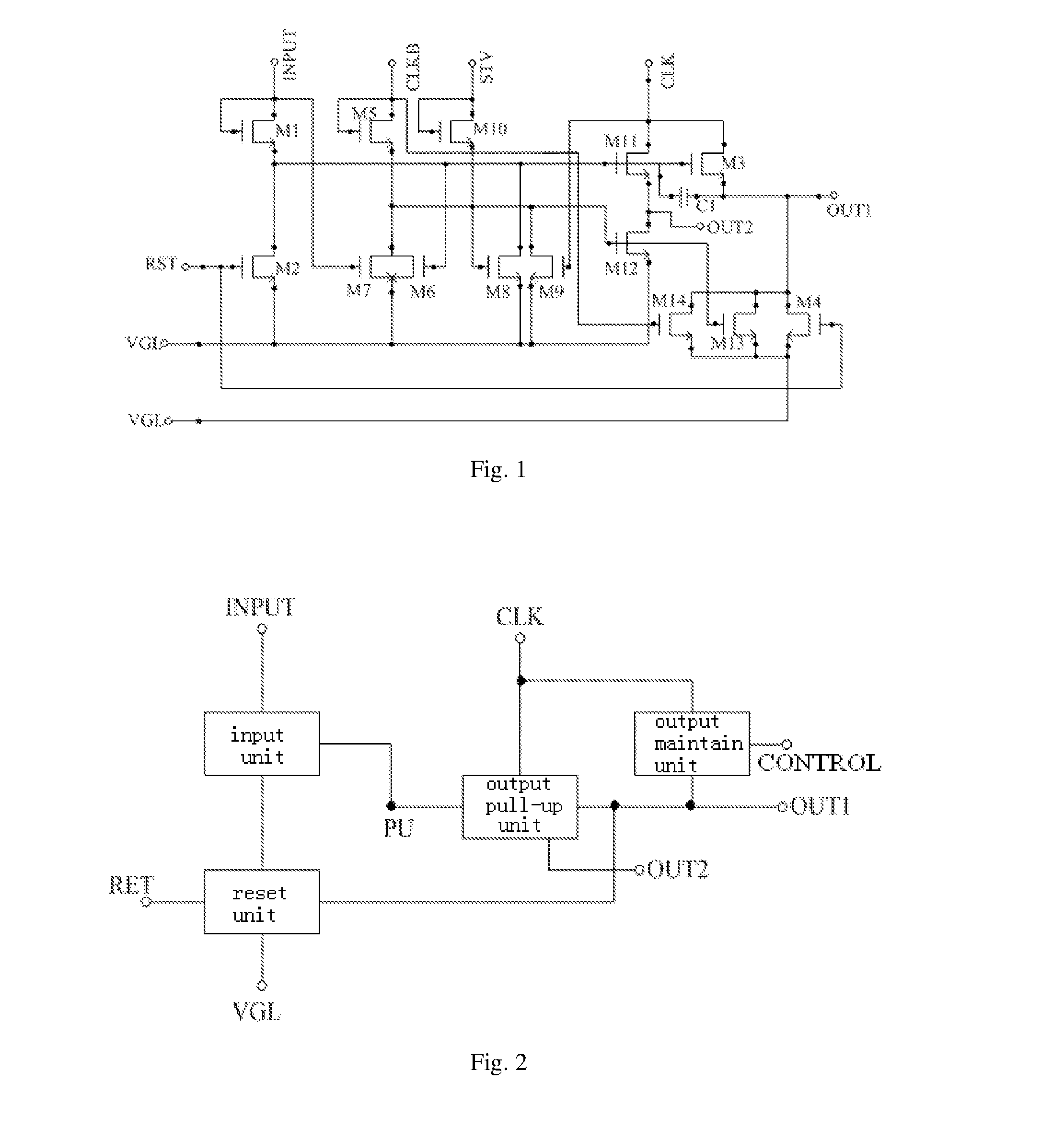
[0037]As shown in FIG. 2, the present embodiment provides a shift register, comprising an input unit, an output pull-up unit, a reset unit and an output maintaining unit, wherein, the input unit is connected with a signal input terminal INPUT, the reset unit and a pull-up control node PU, and is configured to control potential of the pull-up control node PU in accordance with signal inputted from the signal input terminal INPUT; the pull-up control node PU is a connection node between the input unit and the output pull-up unit; the output pull-up unit is connected with a first signal output terminal OUT1, a second signal output terminal OUT2, a first clock signal input terminal CLK, the reset unit and the pull-up control node PU, and is configured to control output of the first signal output terminal OUT1 in accordance with potential of the pull-up control node PU and signal inputted from the first clock signal input terminal CLK; the reset unit is connected with a reset signal inpu...


PUM


Abstract

The present invention provides a shift register, a gate driving circuit and a display device. The shift register comprises an input unit, an output pull-up unit, a reset unit and an output maintaining unit, the input unit is connected with a signal input terminal, the reset unit and a pull-up control node, and the pull-up control node is a connection node between the input unit and the output pull-up unit; the output pull-up unit is connected with a first signal output terminal, a second signal output terminal, a first clock signal input terminal, the reset unit and the pull-up control node; the reset unit is connected with a reset signal input terminal, a low voltage power supply terminal, the input unit and the output pull-up unit; the output maintaining unit is connected with the first clock signal input terminal, the first signal output terminal and a control signal input terminal.

Description

FIELD OF THE INVENTION[0001]The present invention relates to the field of display technology, and particularly relates to a shift register, a gate driving circuit and a display device.BACKGROUND OF THE INVENTION[0002]A thin film transistor liquid crystal display (TFT-LCD) device displays a frame of picture by sequentially, from top to bottom, enabling each line of pixels by inputting a square wave with a certain width through a gate driving circuit and then outputting required signals for each line of pixels from top to bottom through a source driving circuit.[0003]Currently, most of TFT-LCD devices are provided with a gate driving circuit and a source driving circuit on outer side of a display panel, resulting in a high cost. Thus, in other alternatives, a gate driving circuit composed of multiple stages of shift registers is manufactured on a substrate, that is, a design of gate-drive-on-array (GOA) circuit is employed.[0004]Generally, a gate driving circuit has an output timing i...

Claims


Application Information

Patent Timeline
Patent Type & Authority Applications(United States)
IPC IPC(8): G11C19/28G09G3/36
CPCG11C19/28G09G3/3648G09G2300/0426G09G2310/0289G09G2310/08G09G2310/0286G09G2310/0248G09G3/3677G09G2300/0408
Inventor ZHENG, HAOLIANGSHANG, GUANGLIANG
Owner BOE TECH GRP CO LTD
Learn More