
Method and apparatus for developing a flight path

a flight path and flight path technology, applied in the direction of process and machine control, navigation instruments, instruments, etc., can solve the problems of unsuitable manual ground based inspection methods, unsuitable for large linear infrastructure networks, and slowness of inspection methods,

Inactive Publication Date: 2016-10-13
SPATIAL INFORMATION SYST RES
View PDF3 Cites 50 Cited by
  • Summary
  • Abstract
  • Description
  • Claims
  • Application Information

AI Technical Summary

Benefits of technology

The present invention provides a method and apparatus for developing a flight path for precision flying over an area of interest. The method involves determining coordinate and elevation data relating to the area of interest, and using this data to determine a flight path that includes precision paths and non-precision paths. The non-precision paths connect the precision paths and help to control the aircraft's operation. The path data is generated using an aircraft flight path model and sensor coverage and deployment parameters. The method can be used to develop a flight path for sensing or deployment purposes. The technical effect of the invention is to provide a more efficient and effective means of developing a flight path for precision flying over an area of interest.

Problems solved by technology

Surveying of infrastructure, such as roads, powerlines, pipelines, or the like is problematic as such infrastructure can extend over long distances and often has limited accessibility.
Consequently, these are often not suitable for manual ground based inspection methods.
Whilst crawling robots have been proposed for inspecting linear infrastructure, these are typically slow and therefore unsuitable for use in inspecting large linear infrastructure networks, such as powerline networks, which include over 150,000 km of power lines in Queensland alone.
However, this also suffers from a number of drawbacks.
The complex and distributed nature of network infrastructure typically requires manual generation of flight plans, which are labour intensive to generate and have a high degree of variability depending on the preferences and experience of the person doing the planning.
For example, the planning for small sections of network (<1500 km) often takes longer to develop than the actual flight time required for network capture.
Additionally, such manual methods also do not lend themselves to assessment of overall flight path lengths or capture of network spurs, meaning the resulting flight paths are often extremely inefficient.
The planning process also gives little consideration to the sensor operational parameters relative to aircraft roll angle, meaning it is often not feasible to capture infrastructure for some planned flight paths.
The planned paths must be flown manually, which coupled with a lack of feedback from sensors, means that pilots must maintain the position of the aircraft to ensure that the infrastructure remains in the sensor capture footprint, resulting in variable and inefficient implementation, problems with pilot fatigue and major safety issues.
The system also allows for limited control of aircraft position in a 2D plane using existing commercial autopilots.
However, the ability of this system is limited as it does not consider altitude, pitch or speed control, surrounding terrain, or no-fly regions, such as weather obstacles, or the like.
Consequently not all developed flight paths can be flown, and it is still necessary for pilots to control the altitude of the aircraft, which while assisting, does not completely mitigate the extreme burden on the pilot.
Another key limitation of the approach is the necessity to perform manual survey path planning and flight line extraction, which results in inefficiencies in flight planning processes, and in particular does not allow for optimisation of both on and off-survey paths collectively, resulting in efficient flight paths and compromising of inspection objectives.

Method used


Image

  • Method and apparatus for developing a flight path
  • Method and apparatus for developing a flight path
  • Method and apparatus for developing a flight path

Examples


Embodiment Construction

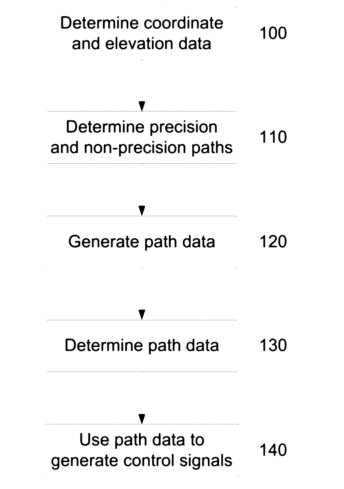
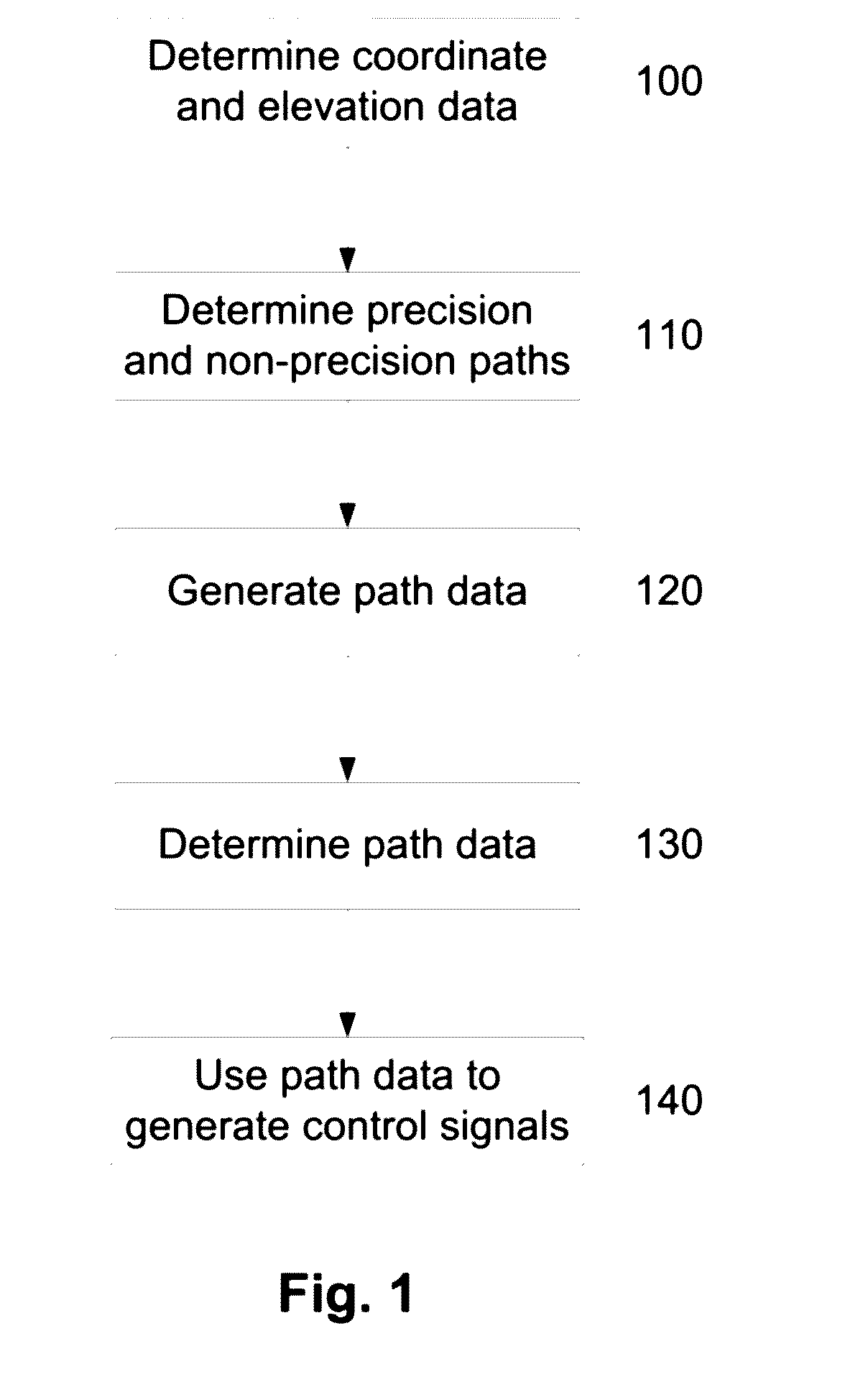
[0297]A method of developing a flight path and a method of controlling an aircraft for precision flying, such as infrastructure surveying, will now be described with reference to FIG. 1.

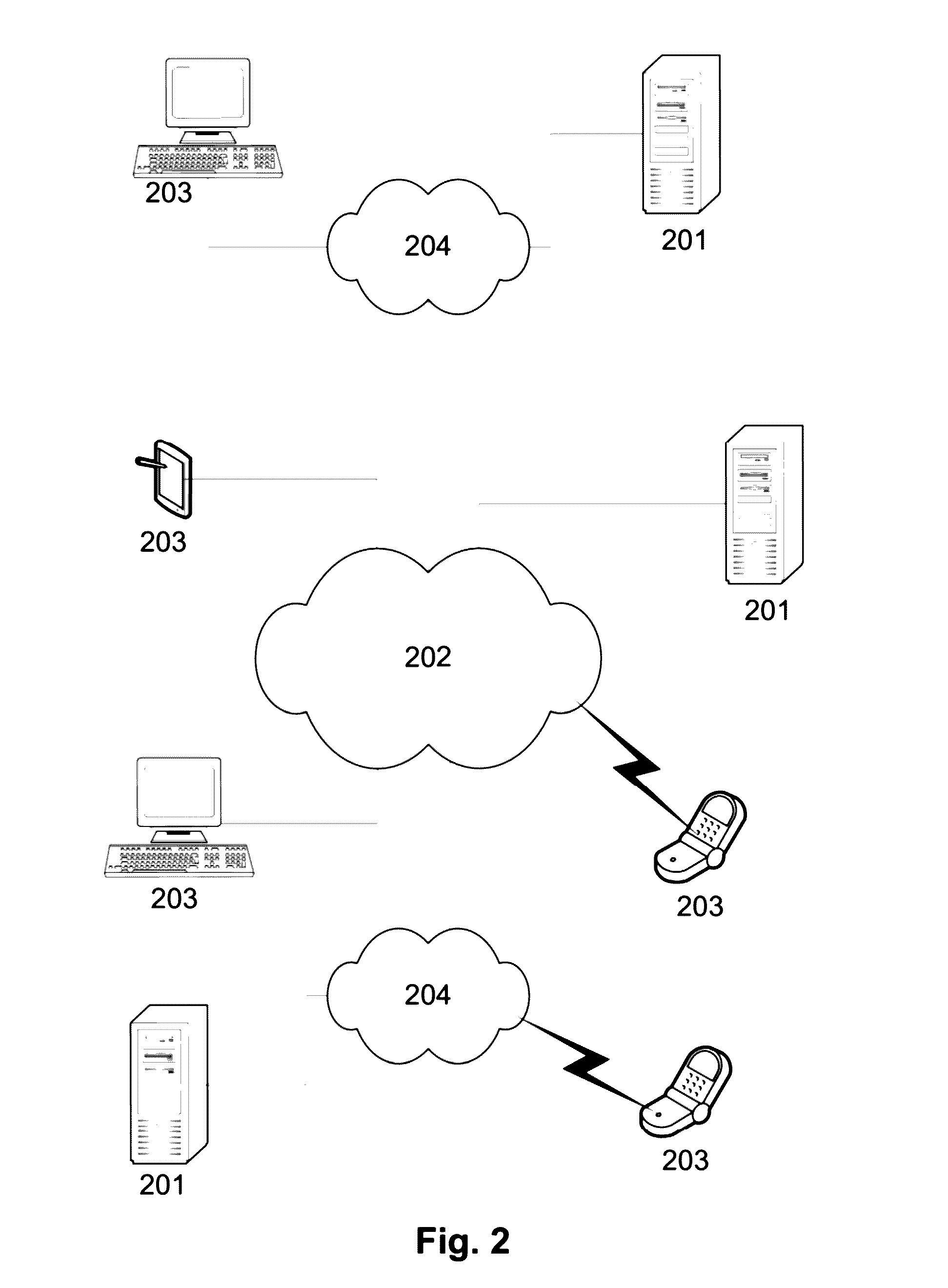
[0298]In this example, it is assumed that the process is performed at least in part using an electronic processing device forming part of a processing system, which may be connected to one or more other computer systems via a network architecture.

[0299]It is also further assumed that control of the aircraft is typically performed using a flight control system, such as a commercial autopilot, with an electronic processing device in communication with the flight control system. In this regard, the electronic processing device used for developing the flight plan and communicating with the flight control system may be the same electronic processing device or may be different electronic processing devices, as will be described in more detail below.

[0300]The term “precision flying” refers to flying in a co...


PUM


Abstract

A method of developing a flight path for precision flying over an area of interest, the method including, in an electronic processing device, determining coordinate and elevation data relating to an area of interest, using the coordinate and elevation data to determine a flight path including precision paths corresponding to precision flying trajectories and non-precision paths interconnecting at least some of the precision paths, and generating path data at least partially indicative of the flight path, the path data being useable in generating control signals for at least partially controlling operation of the aircraft, in use.

Description

BACKGROUND OF THE INVENTION[0001]The present invention relates to a method and apparatus for developing a flight path and a method and apparatus for controlling an aircraft, particularly for use in sensing or deployment within an area of interest, for example for infrastructure surveying.DESCRIPTION OF THE PRIOR ART[0002]The reference in this specification to any prior publication (or information derived from it), or to any matter which is known, is not, and should not be taken as an acknowledgment or admission or any form of suggestion that the prior publication (or information derived from it) or known matter forms part of the common general knowledge in the field of endeavour to which this specification relates.[0003]Surveying of infrastructure, such as roads, powerlines, pipelines, or the like is problematic as such infrastructure can extend over long distances and often has limited accessibility. Consequently, these are often not suitable for manual ground based inspection meth...

Claims


Application Information

Patent Timeline
IPC IPC(8): G05D1/00G05D1/08G01C5/00G05D1/04G01C23/00G01S17/89G05D1/06B64D31/06
CPCG05D1/0094G05D1/0607G05D1/0808G01C5/005G05D1/044G01C23/005G01S17/89B64D31/06G01C7/02G01C15/02G05D1/106
Inventor BRUGGEMAN, TROYFORD, JASON
Owner SPATIAL INFORMATION SYST RES
Learn More