Lower Extremity Receiving Device for Providing Enhanced Leg Mobility During Lower Body Exercise
a receiving device and lower extremity technology, applied in the field of lower extremity receiving devices, can solve the problems of slipping up the leg, preventing optimal gluteal exercise, and affecting exercise even further, and achieve the effect of facilitating the delivery of force of resistan
- Summary
- Abstract
- Description
- Claims
- Application Information
AI Technical Summary
Benefits of technology
Problems solved by technology
Method used
Image

Examples
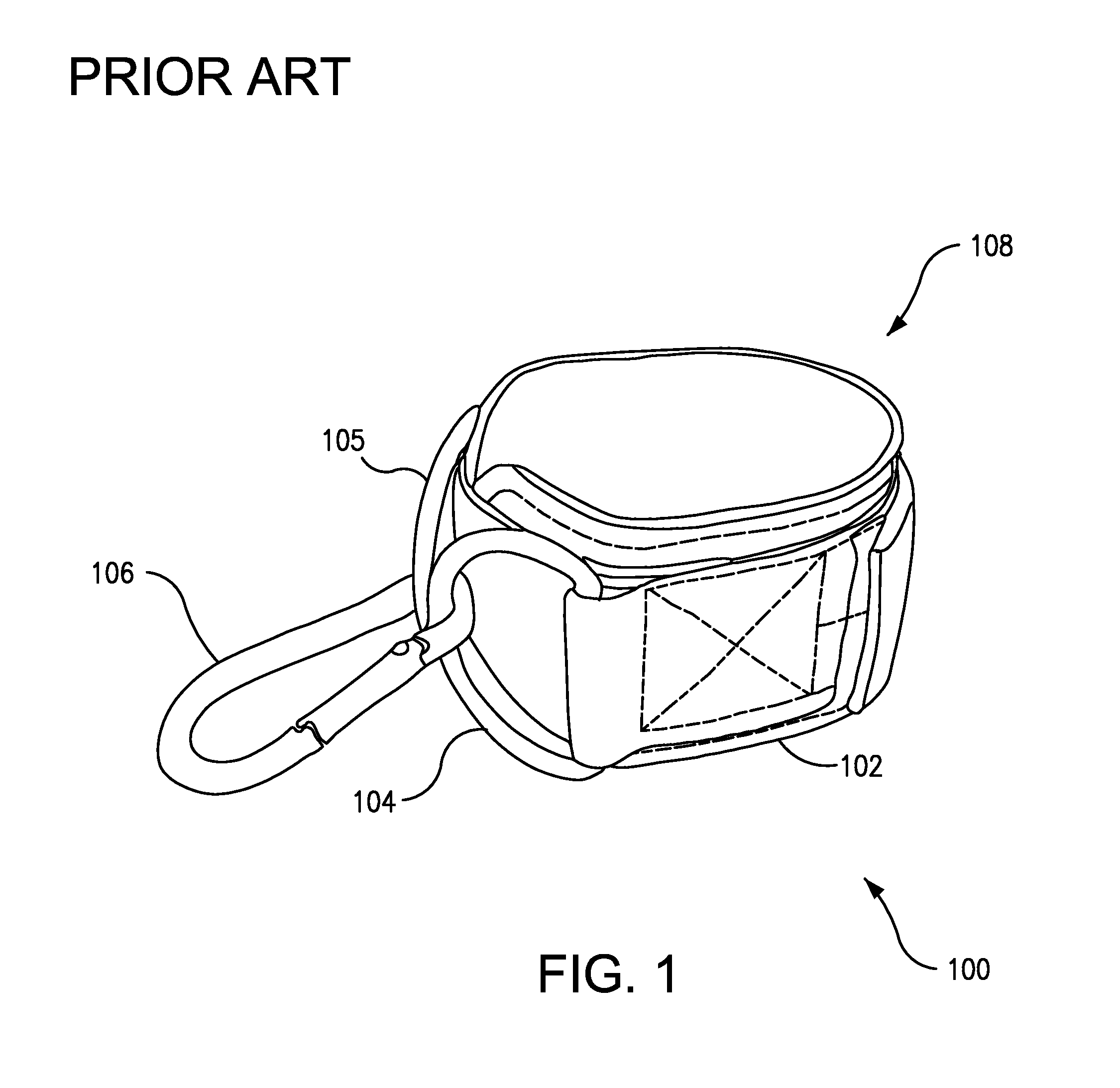
embodiment 100
[0047]The ankle strap 100 is adjustable in the loop that it makes. The band 102 can be adjusted to fit snugly around a given user's posterior leg, at or adjacent to the ankle area. While the embodiment 100 shown makes use of a hook-and-loop system (e.g., Velcro), other adjustment means can be contemplated, such as a belt for example. The rings 104, 105 shown in FIG. 1 are D-rings. Their semicircular shape allows the locking loop 106 to slide up and down their extent, enabling a user to exercise their leg in a variety of ways, under resistance.
[0048]These functionalities make the ankle strap 100 considerably useful for hip extension and / or hip abduction exercises, which strengthen the gluteal muscles. However, several limitations prevent optimal gluteal exercise. Although it is advantageous to switch legs frequently during exercise, this strap 100 must be meticulously applied manually to each leg, either by using two straps, applying one to each legs and switching the line from one l...
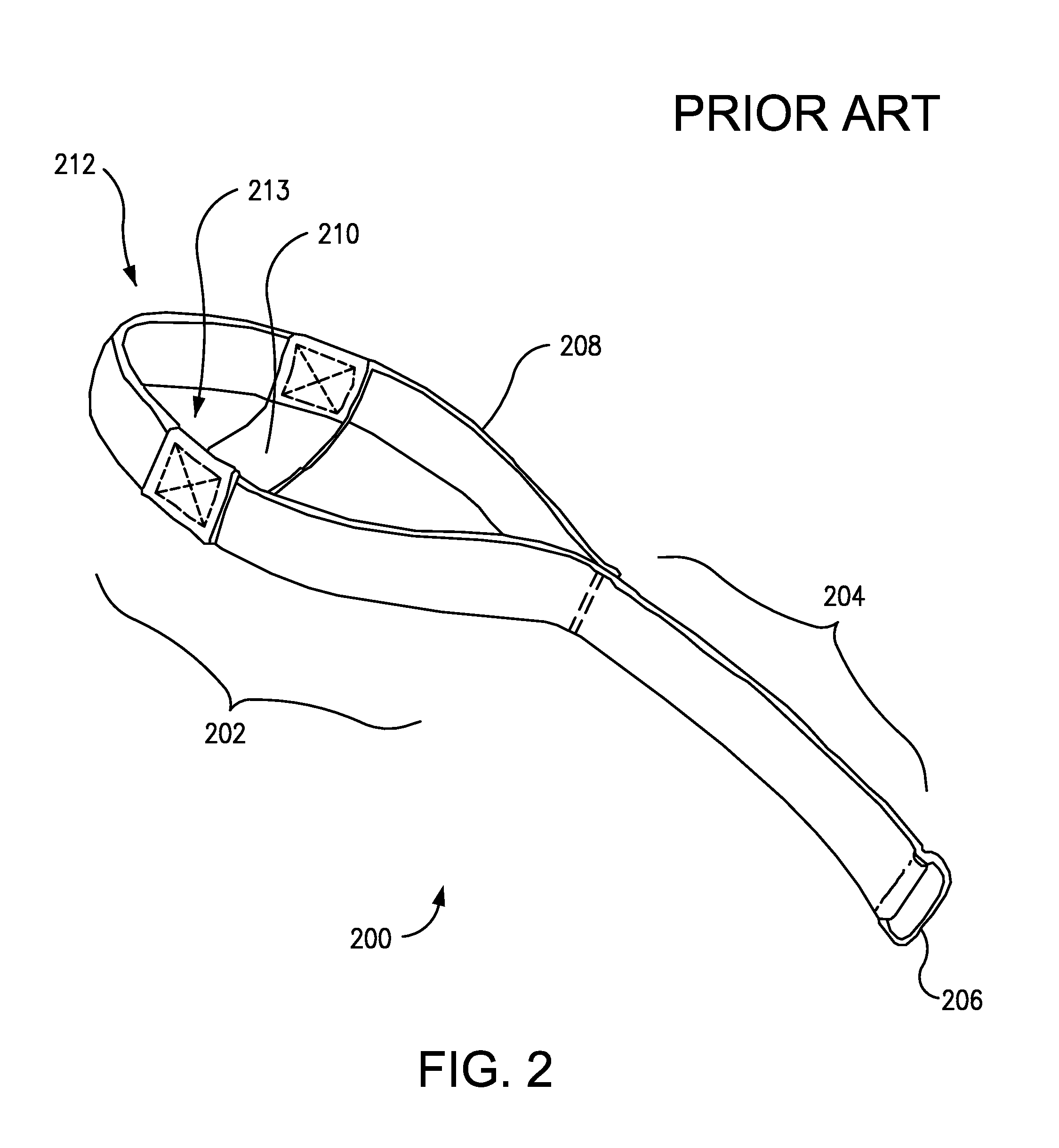
embodiment 400
[0060]FIG. 4 is an unembellished illustrative embodiment 400 of the invention. The embodiment shown 400 comprises a self-standing sling configured to wrap securely around a portion of a user's lower extremity, and a resistance harness connected to the sling and capable of delivering resistance to the sling. The sling includes a supportive scaffold 402 to help the sling stand up and open. The resistance harness shown includes a band 404 connected to the sling, and a ring 406 for engaging a resistance-transmitting line 407 and thereby facilitating delivery of force of resistance from the line 407 to the sling.
[0061]The sling further includes a heel socket 408 for receiving a user's heel in the case of hip extension exercise. The heel socket 408 shown here is a circular hole, but it can take other structural forms and / or assume other shapes, as further shown and described below. In the case of substantial hip abduction exercise, the heel socket 408 is not used in its capacity to hold t...
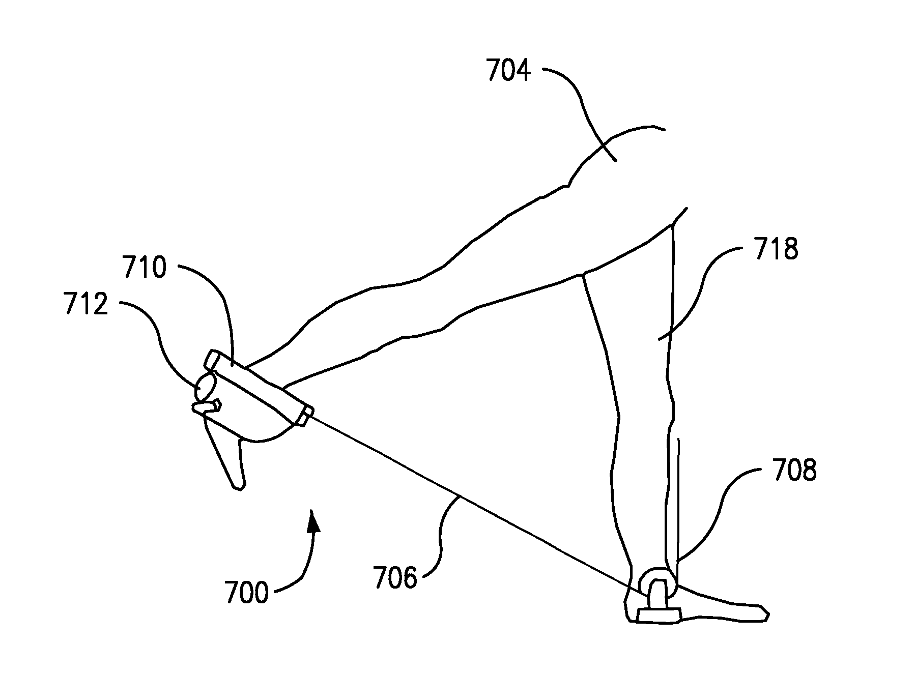
embodiment 800
[0087]FIG. 8 is a rear oblique view of an embodiment 800 of the invention wrapped around a user's posterior leg and foot during hip extension exercise. A user pulls their exercising leg 802 back to extend their hip, while the device 800 absorbs resistance from a resistance-transmitting line 804 in communication with a pulley 806. The device 800 includes a supportive scaffold with two supportive walls 808, 809 and an upper band with two loops 810, 811 for housing a belt harness 812.
[0088]The loops 810, 811 can be sewn, glued or even screwed to the body of the sling, as a few exemplary means of attachment. In some embodiments, the loops 810, 811 can be selectively opened and closed, for example by Velcro attachment or by zipper along a lengthwise seam. This can facilitate insertion of the belt harness 812 into the loops 810, 811, which can be opened to allow the harness 812, and then closed to secure and fasten the harness 812. A ring 814 connects the belt harness 812 to the resistanc...
PUM
 Abstract
Description
Claims
Application Information
 - R&D
- Intellectual Property
- Life Sciences
- Materials
- Tech Scout
- Unparalleled Data Quality
- Higher Quality Content
- 60% Fewer Hallucinations
Browse by: Latest US Patents, China's latest patents, Technical Efficacy Thesaurus, Application Domain, Technology Topic, Popular Technical Reports.
© 2025 PatSnap. All rights reserved.Legal|Privacy policy|Modern Slavery Act Transparency Statement|Sitemap|About US| Contact US: help@patsnap.com