
Sewing Machine

Active Publication Date: 2016-09-22
JANOME CORP
View PDF65 Cites 7 Cited by
  • Summary
  • Abstract
  • Description
  • Claims
  • Application Information

AI Technical Summary

Benefits of technology

The invention allows the sewing machine to detect how thick a cloth is and how stretchy it is when there is no pressure applied. By using this information, the machine can set the sewing condition to improve the quality of the sewing and stitch work.

Problems solved by technology

When the seam is too tight, a cloth with high stretch properties, such as a jersey cloth or a knit cloth, causes a material puckering, and when the seam is too loose, the threads are likely to come apart from each other.
In addition, when a stitchwork formation is performed on a cloth with high stretch properties like a quilt, the actual height of the presser foot is likely to be lower than the set distance relative to the cloth, causing an improper sewing.
When the stop height of the presser foot is set as the thickness of a cloth, the thickness of the cloth depressed by the presser foot is to be detected, and thus it is difficult to detect the thickness of the cloth when no load is applied.
That is, the depress amount of a cloth by the presser foot varies depending on the cloth type, and it is difficult to set the thickness of the cloth when no load is applied based on the thickness of the depressed cloth.
Hence, according to conventional cloth-thickness detecting schemes, it is difficult to set a sewing condition in accordance with the thickness of a cloth when no load is applied, which does not contribute to an improvement of sewing quality and stitchwork quality.
In fact, when an actual difference between the thickness of the cloth when no load is applied and the thickness of the cloth based on the conventional cloth-thickness detection is large, a sewing condition set up based on the conventional schemes sometimes results in a deterioration of sewing quality and stitchwork quality.

Method used


Image

  • Sewing Machine
  • Sewing Machine
  • Sewing Machine

Examples


Embodiment Construction

Entire Structure of Sewing Machine

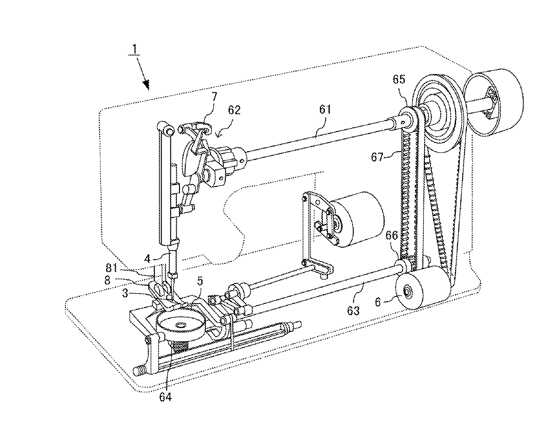
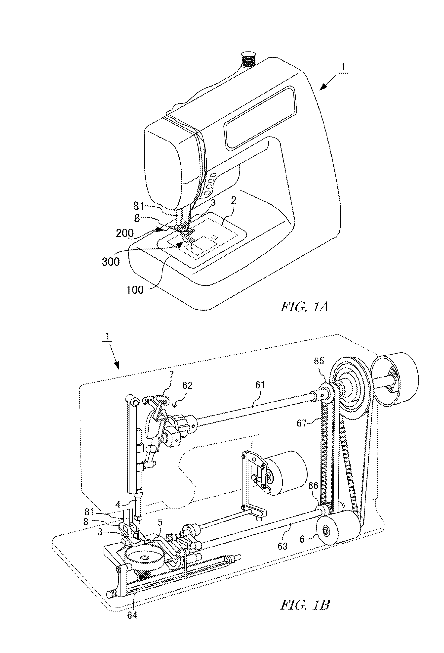
[0037]As illustrated in FIG. 1, a sewing machine 1 is a home, professional or industrial machine that locates a needle 3 while holding a cloth 100 mounted on a needle plate 2 by a presser foot 8, and intertwines a needle thread 200 with a bobbin thread 300, thereby forming a seam. This sewing machine 1 includes a needle bar 4 and a hook 5. The needle bar 4 extends vertically relative to the needle plate 2, and is attached so as to be movable up and down along the vertical direction. This needle bar 4 supports, at a tip toward the needle plate 2, the needle 3 that holds the needle thread 200. The hook 5 is formed in a hollow drum shape with an open plane, is attached horizontally or vertically relative to the needle plate 2, and is rotatable around the circumferential direction. In this embodiment, the hook 5 is attached horizontally. This hook 5 stores thereinside a bobbin around which a bobbin thread 300 is wound.

[0038]According to this sewing mach...


PUM


Abstract

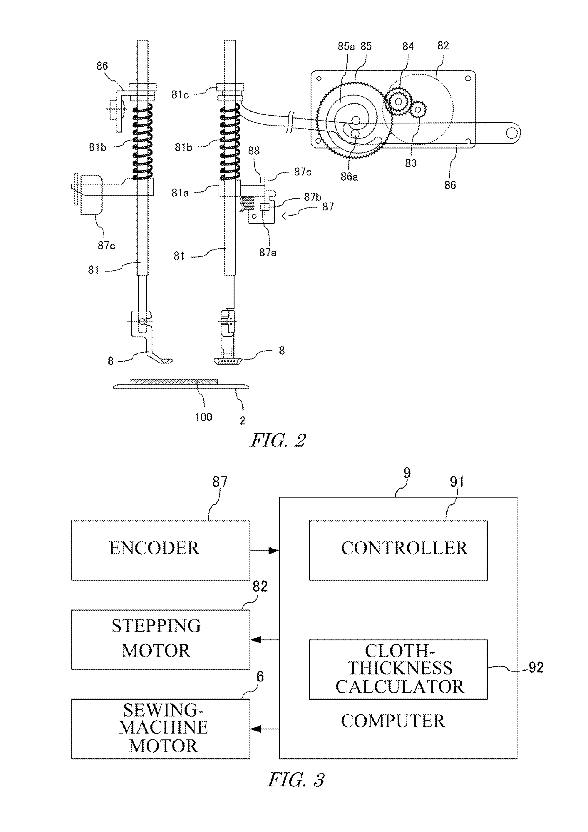
A sewing machine moves a presser foot up and down through a presser-bar lifting lever to depress a cloth. The lever is moved down by a stepping motor at a constant move-down amount. A compression spring is present between the stepping motor and the presser foot. The compression spring is compressed by some of the constant move-down amount of the lever, and applies, to the presser foot, pushing force canceling repulsive force from the depressed cloth. The move-down amount of the presser foot is detected by an encoder, and a thickness of the cloth is calculated by a cloth-thickness calculator. The cloth-thickness calculator performs calculation based on the move-down amounts at two timings in a time period at which the presser foot depresses the cloth and attempts to further move down.

Description

CROSS-REFERENCE TO RELATED APPLICATION[0001]This application is based upon and claims the benefit of priority from Japan Patent Application No. 2015-058102, filed on Mar. 20, 2015, the entire contents of which are incorporated herein by reference.FIELD OF THE INVENTION[0002]The present invention relates to a stitchwork sewing machine.BACKGROUND[0003]Sewing by a sewing machine is performed while a cloth is held by a presser foot. The presser foot has a primary function of suppressing, when a needle is pulled out from a cloth, an uplifting of the cloth associated with the pulled-out needle. In addition, the presser foot has a secondary function of holding the cloth together with a feed dog, and smoothly feeding the cloth. In order to fully accomplish such functions, it is necessary to appropriately control depress force applied to the cloth from the presser foot.[0004]A sewing machine intertwines a needle thread with a bobbin thread, thereby forming a seam. When the seam is too tight,...

Claims


Application Information

Patent Timeline
IPC IPC(8): D05B29/02D05B73/12D05B47/04D05B19/16D05B29/12
CPCD05B29/02D05B19/16D05B73/12D05B47/04D05B29/12D05D2209/16
Inventor KOIKE, MIKIOMAFUNE, JUN
Owner JANOME CORP
Learn More