
Breathing apparatus

a breathing apparatus and breathing technology, applied in the field of breathing apparatus, can solve the problems of many elements and disadvantages of actual products, and achieve the effect of easy assembly of breathing apparatus

Inactive Publication Date: 2016-09-22
SHIGEMATSU WORKS CO LTD
View PDF7 Cites 9 Cited by
  • Summary
  • Abstract
  • Description
  • Claims
  • Application Information

AI Technical Summary

Benefits of technology

This patent relates to a breathing apparatus with a voice conductor for maintaining airway patentcy. The technical effects include: 1. The Hall element, a magnetometric sensor, is not easily degraded by particulate matter, making it less susceptible to contamination. 2. The formed sheet body, which does not require tensile force, can keep a flat condition, even when not in use. This simplifies the overall structure of the breathing apparatus. 3. The simple structure of the vibration member allows for easier assembly of the breathing apparatus. 4. The breath monitoring apparatus can detect and filter out high-frequency vibration caused by the user's breath, and prevent it from interfering with the function of the breathing apparatus. 5. The low-pass filter removes high-frequency components from the detection signal, preventing the battery from discharging rapidly, deteriorating the electronics components, and reducing the overall accuracy of the control of the motor fan. 6. The small deflection of the vibration member due to changes in internal pressure of the face piece is minimized, resulting in a more accurate detection of the user's breath. 7. The breath monitoring apparatus, voice conductor, and controller can be assembled as a single unit, making assembly easier.

Problems solved by technology

Thus, the actual product has a disadvantage in that it comprises many elements.

Method used


Image

  • Breathing apparatus
  • Breathing apparatus
  • Breathing apparatus

Examples


Embodiment Construction

[0033]A breathing apparatus in accordance with a preferred embodiment of the present invention will be described.

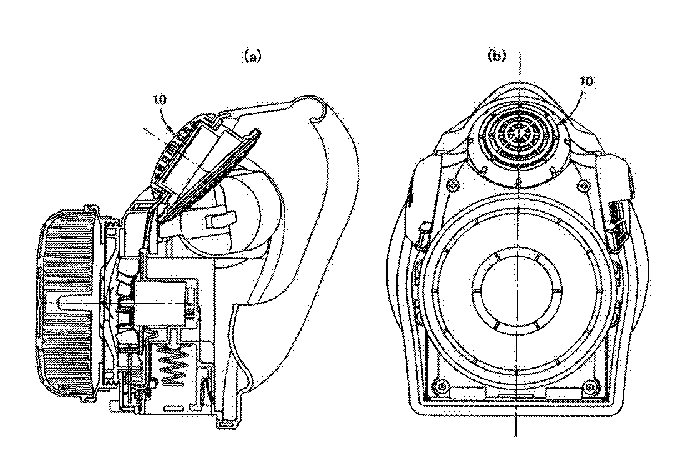
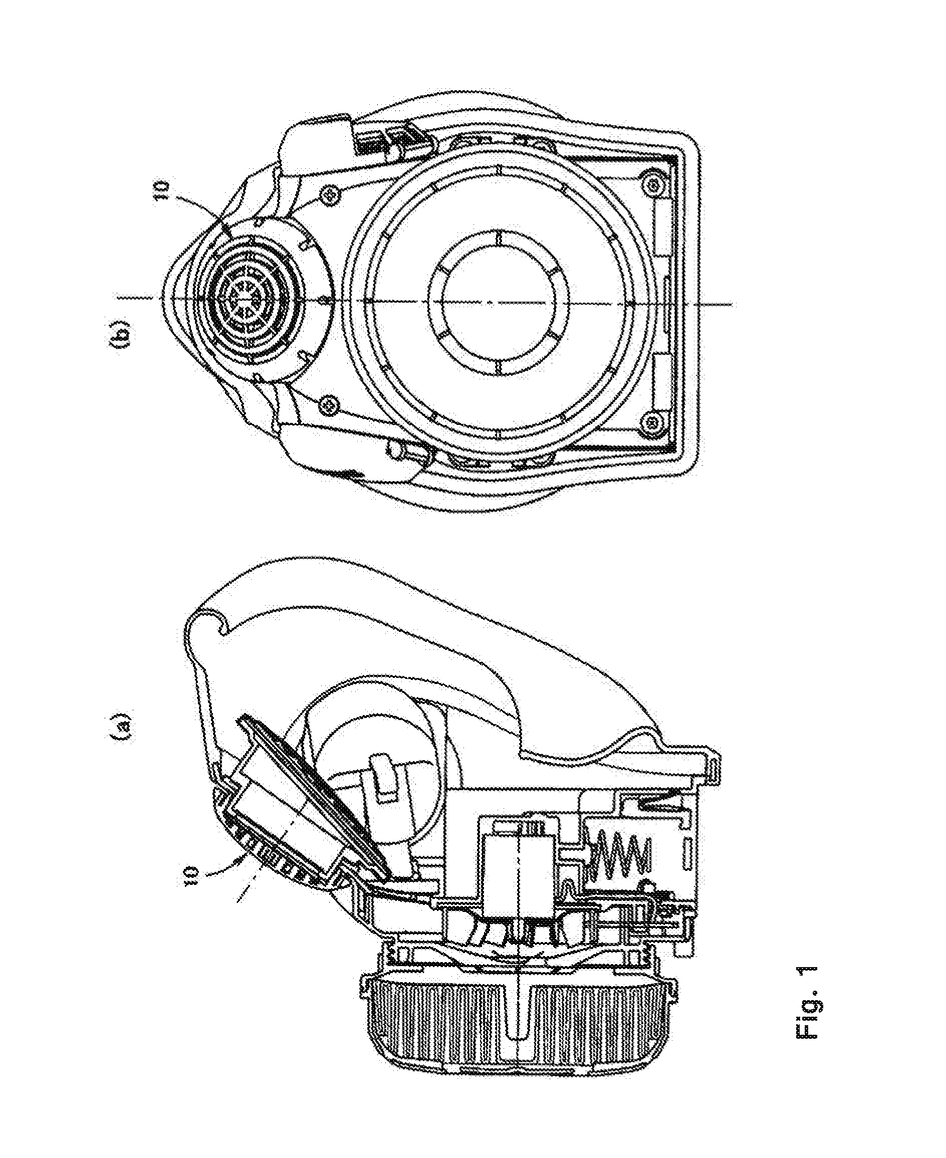
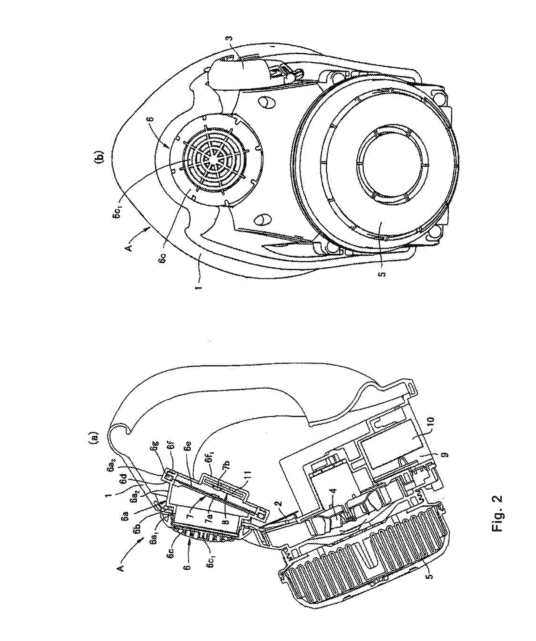
[0034]As shown in FIG. 2, a breathing apparatus A comprises a bowl-shaped half face type face piece 1 for covering a nose and a mouth of a user's face, an inhale valve 2 and an exhale valve 3 which are formed as reed valves, a motor fan 4 located upstream of the inhale valve 2 in relation to the inhale air flow so as to supply external air into the face piece 1 through the inhale valve 2, a filter 5 located upstream of the motor fan 4 in relation to the inhale air flow so as to clean the external air sucked into the motor fan 4, and a voice conductor 6. The inhale valve 2, the exhale valve 3, the motor fan 4, the filter 5 and the voice conductor 6 are attached to the face piece 1.

[0035]As shown in FIGS. 2 and 3, the voice conductor 6 comprises a cylindrical body 6a provided with a small diameter portion 6a1, a middle diameter portion 6a2 and a large diameter portion 6a3 a...


PUM


Abstract

An object of the present invention is to provide a breathing apparatus whose a breath monitoring apparatus does not comprise an inhale valve or an exhale valve and whose number of elements is less than that of the conventional breathing apparatus. A breathing apparatus comprises a face piece for covering the whole face or part of the face, an inhale valve, an exhale valve, a voice conductor, a motor fan for supplying external air into the face piece through the inhale valve, a filter for cleaning the external air sucked into the motor fan, a breath monitoring apparatus not comprising the inhale valve or the exhale valve, and a controller for controlling the operation of the motor fan synchronously with the breath based on the detection signal from the breath monitoring apparatus, wherein the inhale valve, the exhale valve, the voice conductor, the motor fan, the filter, the breath monitoring apparatus and the controller are attached to the face piece, and wherein the breath monitoring apparatus detects deflection of a vibration member of the voice conductor.

Description

TECHNICAL FIELD[0001]The present invention relates to a breathing apparatus.BACKGROUND ART[0002]In Patent Document No. 1, the applicant of the present application disclosed a breathing apparatus comprising a face piece for covering the whole face or part of the face, an inhale valve, an exhale valve, a motor fan for supplying external air into the face piece through the inhale valve, a filter for cleaning the external air sucked into the motor fan, a breath monitoring apparatus not comprising the inhale valve or the exhale valve, and a controller for controlling the operation of the motor fan synchronously with the breath based on the detection signal from the breath monitoring apparatus, wherein the inhale valve, the exhale valve, the motor fan, the filter, the breath monitoring apparatus and the controller are attached to the face piece, and wherein the breath monitoring apparatus comprises a diaphragm covering an opening formed in the face piece, a magnet attached to the diaphrag...

Claims


Application Information

Patent Timeline
Patent Type & Authority Applications(United States)
IPC IPC(8): A62B18/08A62B9/02A62B18/00A62B18/10A62B23/02A62B7/10A62B18/02
CPCA62B18/08A62B7/10A62B9/02A62B18/006A62B18/10A62B23/025A62B18/025A62B18/02A62B18/088
Inventor HANAOKA, YUKIONO, KENICHIIDE, HIROYUKI
Owner SHIGEMATSU WORKS CO LTD
Learn More