
Dynamically adjusting surveillance devices

a technology of surveillance device and dynamic adjustment, which is applied in the direction of television system, instruments, image enhancement, etc., can solve the problems of reducing the overall cost, affecting the accuracy of the camera, so as to reduce the overall cost, and reduce the cost

Inactive Publication Date: 2016-09-15
KARABED RAZMIK
View PDF3 Cites 3 Cited by
  • Summary
  • Abstract
  • Description
  • Claims
  • Application Information

AI Technical Summary

Benefits of technology

The new Surveyor design of a rotating camera system for surveillance has the advantage of being less expensive and more durable, with better viewing quality and reduced mechanical vibration. This is achieved by eliminating the need for a separate device to rotate the camera. A smaller end switch is also needed for calibration, further reducing costs.

Problems solved by technology

The motor that rotates the camera is a major cost and a potential area for maintenance.
The device that rotates the camera in the conventional design is one of the major cost areas of the dynamically adjustable surveillance device; therefore the elimination of the device that rotates the camera lowers the overall cost.
This elimination makes the end switch used in the calibration of the conventional device useless, therefore further reducing cost.
Since the device that rotates the camera is the major moving part of the conventional surveillance device, it is the most susceptible to wear and tear.

Method used


Image

  • Dynamically adjusting surveillance devices
  • Dynamically adjusting surveillance devices
  • Dynamically adjusting surveillance devices

Examples


example 1

[0057]Example 1 is explained using FIGS. 3, 4, and 6. FIG. 3 gives a block diagram of a dynamically adjusting surveillance system. A camera 10 may be connected to a first processor and memory unit 20. The camera 10 may capture a view containing a key region containing a desired view. The camera 10 may send a wide view signal to the first processor and memory unit 20.

[0058]An angular sensor 60 may be connected to the first processor and memory unit 20. The angular sensor 60 may be configured to detect the angular orientation of a vehicle so that the angular sensor 60 provides an angular position signal to the first processor and memory unit 20.

[0059]A turn signal switch 70 may be connected to the first processor and memory unit 20. The turn signal switch 70 may send a turn indicating signal to the first processor and memory unit 20. The first processor and memory unit 20 may be connected to a display adaptor unit 30.

[0060]When the turn signal switch 70 is on its ‘OFF’ position a) the...

example 2

[0082]Example 2 is explained using FIGS. 3, 5, and 7. Example 2 uses the same block diagram, FIG. 3, as did Example 1 . Therefore, the earlier description of FIG. 3 still apply.

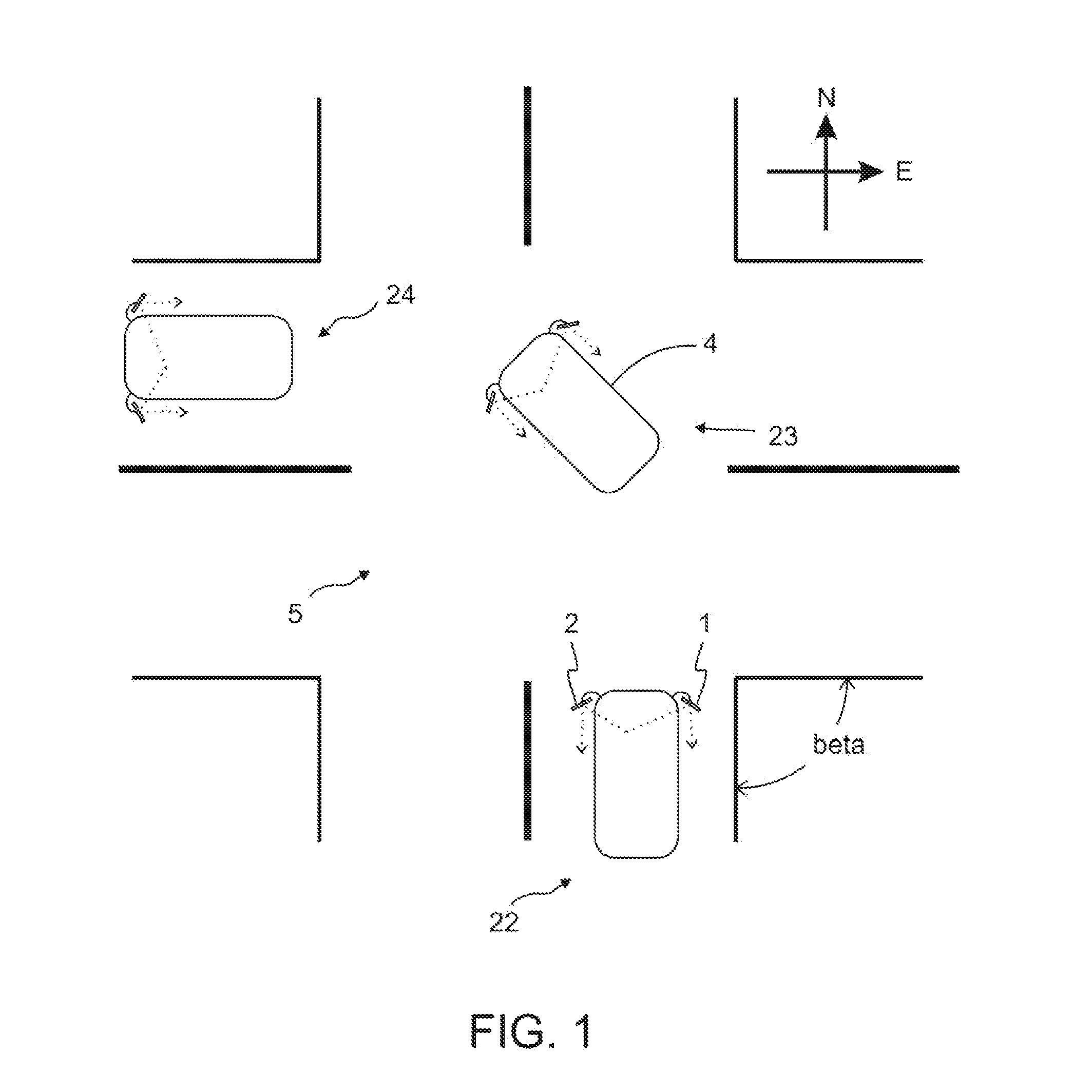
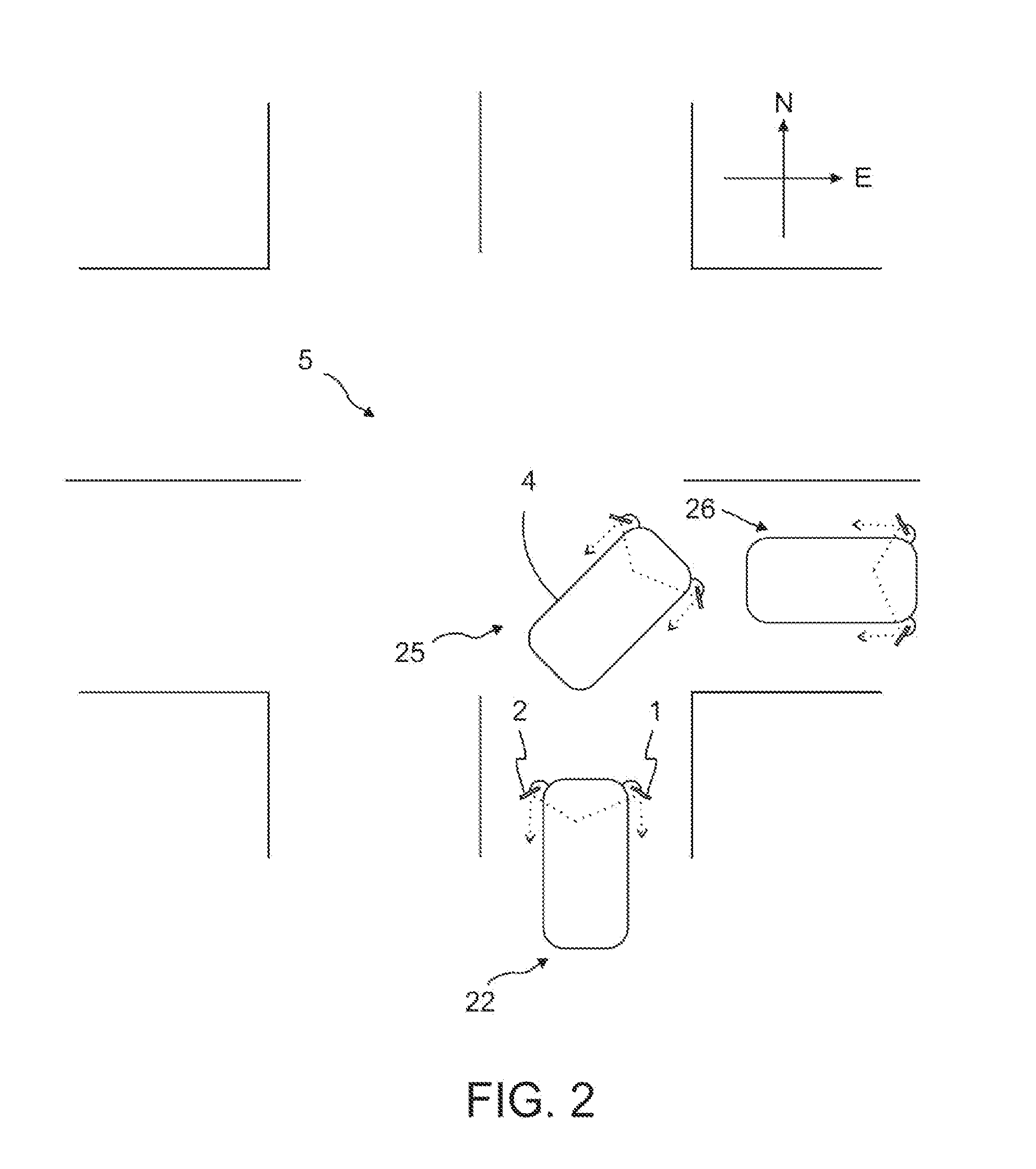
[0083]FIG. 5 depicts the monitor 50, and the camera 10 with respect to the automobile 4 according to Example 2 . Example 2 applies to the right side monitor during left turns. In FIG. 7, the automobile 4, the monitor 50 and the camera 10 are shown in the three positions 22, 23, and 24 of FIG.1.

[0084]At the position 22, facing north, before the turn signal switch 70 is set to its ‘ON’ position, the view signal of the camera 10 corresponds to a view spanning XOY angle, and the key region may be defined by an angle, V1OU1. The desired view is compatible to the view of a traditional right side mirror.

[0085]When the turn signal switch 70 is set to its ‘ON’ position, indicating a left turn (for Example 2 ), the desired view may change quickly to a view of a road section opposite to that of the road section into whi...

example 3

[0097]Example 3 is explained using FIGS. 3, 5, and 8. Example 3 uses the same block diagram, FIG. 3, as did Examples 1 and 2.

[0098]FIG. 5 depicts the monitor 50, and the camera 10 with respect to the automobile 4 according to Example 3 . Example 3 applies to the right side monitor during right turns. In FIG. 8, the automobile 4, the monitor 50 and the camera 10 are shown in the three positions 22, 25, and 26 of FIG. 1.

[0099]At the position 22, facing north, the view signal of the camera 10 corresponds to a view spanning the XOY angle, and the key region may be defined by an angle, V1OU1. The desired view is compatible to the view of a traditional right side mirror.

[0100]When the turn signal switch 70 is set to its ‘ON’ position, indicating a right turn (for Example 3 ), the desired view may become a view of the road section immediately behind the vehicle on the right side before the turn is initiated. Until the right turn is completed, the desired view may stay the same, it faces so...


PUM


Abstract

A dynamically adjusting surveillance system provides a monitor on one or both sides of a vehicle, each monitor including one or more cameras capturing an image that includes a key region. The monitors can display this key region to a driver of the vehicle. The key region can be updated based on the activities of the driver. For example, the key region can change to provide a desirable view for the driver before, during and after a turn is made. An angular sensor can be used to detect the position of the vehicle in the turn to dynamically update the key region displayed to the driver. The key region can be changed at a sufficient frequency so that a gradual and smooth view is provided to the driver during the turn.

Description

RELATED APPLICATIONS[0001]This application relates to, claims priority from, and incorporates herein by reference, as if fully set forth, the following:[0002]1) U.S. Provisional Patent Application Ser. No. 62 / 132384 filed on Mar. 12, 2015 and entitled “Dynamically Adjusting Surveillance Devices”.BACKGROUND OF THE INVENTION[0003]1. Field of the Invention[0004]The invention relates generally to surveillance devices and methods, and more particularly to dynamically adjusting surveillance devices that can, for example, assist a driver when making a turn.[0005]2. Description of Prior Art and Related Information[0006]A large number of car crashes is due to a lack of adequate surveillance during turns at intersections. According to the U.S. Department of Transportation, National Highway Traffic Safety Administration (NHTSA), DOT HS 811 366, September 2010, entitled “Crash Factors in Intersection-Related Crashes: An On-Scene Perspective”, among 12 critical pre-crash events, a vehicle turnin...

Claims


Application Information

Patent Timeline
Patent Type & Authority Applications(United States)
IPC IPC(8): B60R1/00G06T7/60H04N5/247G06T7/00H04N5/232G06K9/00G06K9/52H04N23/90
CPCB60R1/00G06K9/00771G06T7/60G06K9/52G06T2207/30256H04N5/23238H04N5/247G06K9/00798G06K2009/4666G06T7/0042B60R2300/70B60R2300/8026H04N7/181B60R1/28B60R1/26
Inventor KARABED, RAZMIK
Owner KARABED RAZMIK
Learn More