
Conveying Systems and Methods of Use

a conveyor and conveyor technology, applied in the direction of conveyor parts, rollers, roller-ways, etc., can solve the problems of contaminating the fruit or other product being conveyed thereon, requiring cleaning and repair, clogging or damage the system, etc., to minimize the collection of bacteria, fungus and other contaminants at the sidewalls of the roller bed, and prevent damage and wear on the driving system of the conveyor

Active Publication Date: 2016-09-08
REED LORIN
View PDF9 Cites 8 Cited by
  • Summary
  • Abstract
  • Description
  • Claims
  • Application Information

AI Technical Summary

Benefits of technology

The patent is about improving conveyor systems by using a magnetic rotor system that prevents debris and contaminants from getting on the conveyor and causing damage or wear on the system. It also helps to minimize the gap between rollers and retaining walls, which can collect debris. This results in less maintenance required for the conveyor system.

Problems solved by technology

Unfortunately, the gaps between the rollers and the retaining walls and the openings through the side rails allow the passage of water, cleaning solutions, wax, debris, and other materials.
These contaminants may pass from the roller bed through the retaining wall and into the drive system, which may clog or damage the system, requiring cleaning and repair.
Conversely, foreign materials may pass into the system and onto the rollers from the outside, potentially contaminating the fruit or other product being conveyed thereon.
Importantly, any gaps between the lateral ends of the rollers and the retaining walls of the conveyor, as well as the holes in the side rails, may act as a collection site for debris and bacteria, which can result in contamination of the produce on the washing table.
In some systems, rubber seals or bearings may be provided in the shaft support side wall openings to prevent such contamination, but these may only serve to collect and accumulate undesirable contaminants from the conveyed products.
Proper cleaning may be onerous and costly to the operator in terms of both labor and down time.
The disassembly process can be time-consuming and tedious because it may be necessary to disassemble the roller bed and the drive mechanism in order to sufficiently access the interior parts of the conveying system for sanitation and maintenance.
The time required to disassemble and clean and / or repair a conveyor system can result in a loss of production time while the conveyor system is inoperable and a corresponding loss of revenues.
Additionally, the drive system and other components may be damaged over time by the continuous accumulation of materials from the roller bed.
Unfortunately, experience has shown that even regular and thorough cleaning of produce conveyor systems is often not enough to eradicate E.coli and Listeria because these pathogens are capable of surviving in even the smallest and most remote areas.

Method used


Image

  • Conveying Systems and Methods of Use
  • Conveying Systems and Methods of Use
  • Conveying Systems and Methods of Use

Examples


Embodiment Construction

[0065]Reference will now be made in detail to certain embodiments of the invention, examples of which are illustrated in the accompanying drawings. While the invention will be described in reference to these embodiments, it will be understood that they are not intended to limit the invention. To the contrary, the invention is intended to cover alternatives, modifications, and equivalents that are included within the spirit and scope of the invention as defined by the claims. In the following disclosure, specific details are given to provide a thorough understanding of the invention. However, it will be apparent to one skilled in the art that the present invention may be practiced without these specific details.

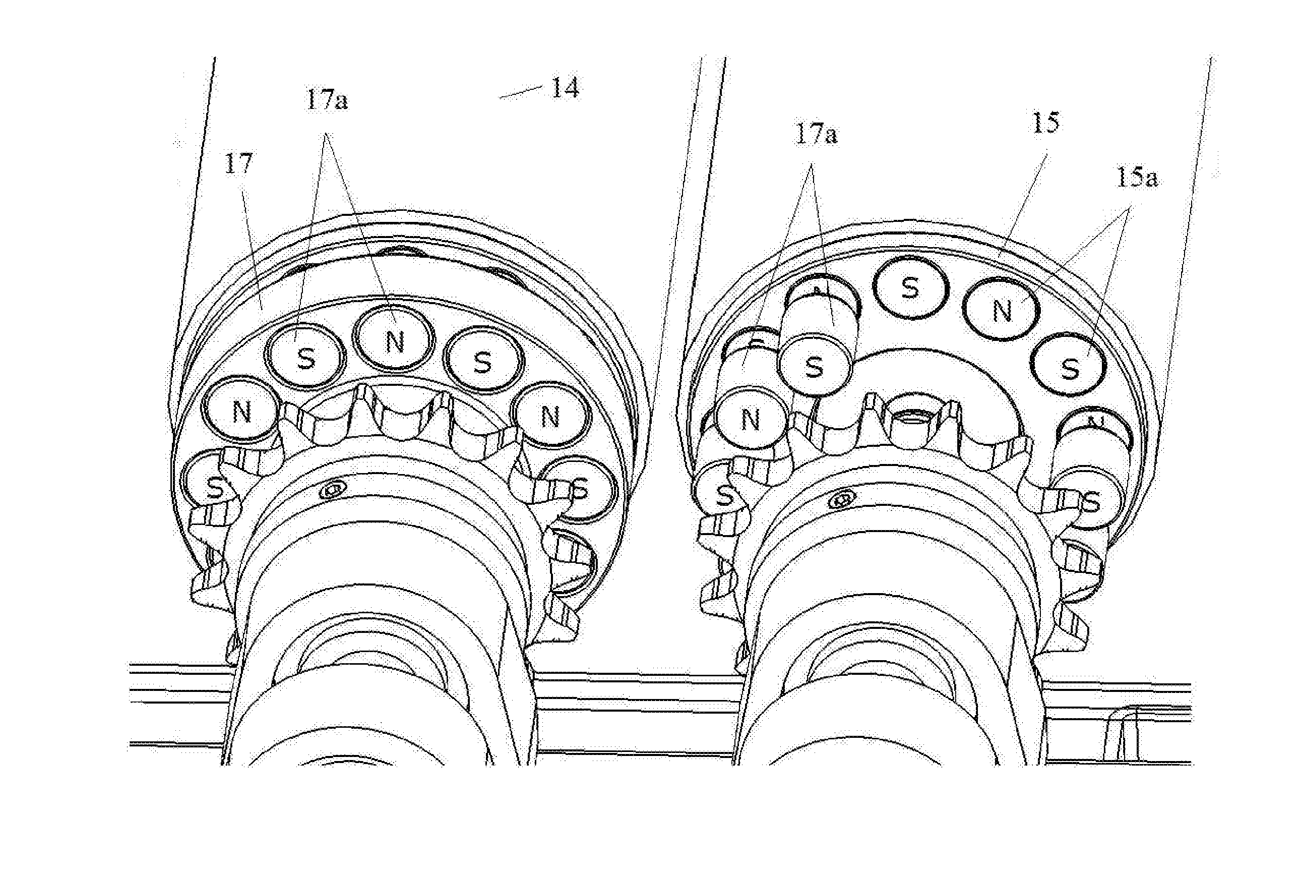
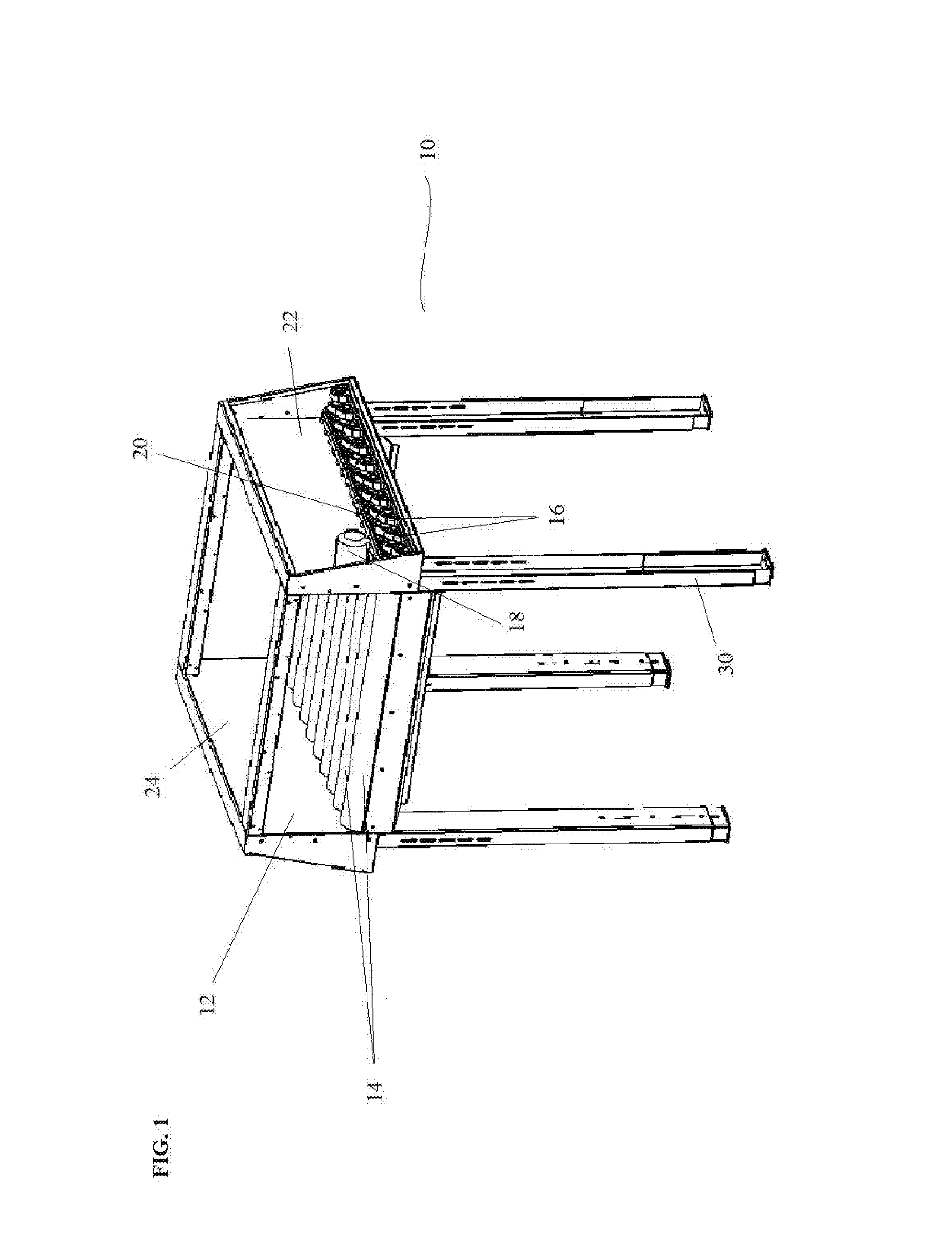
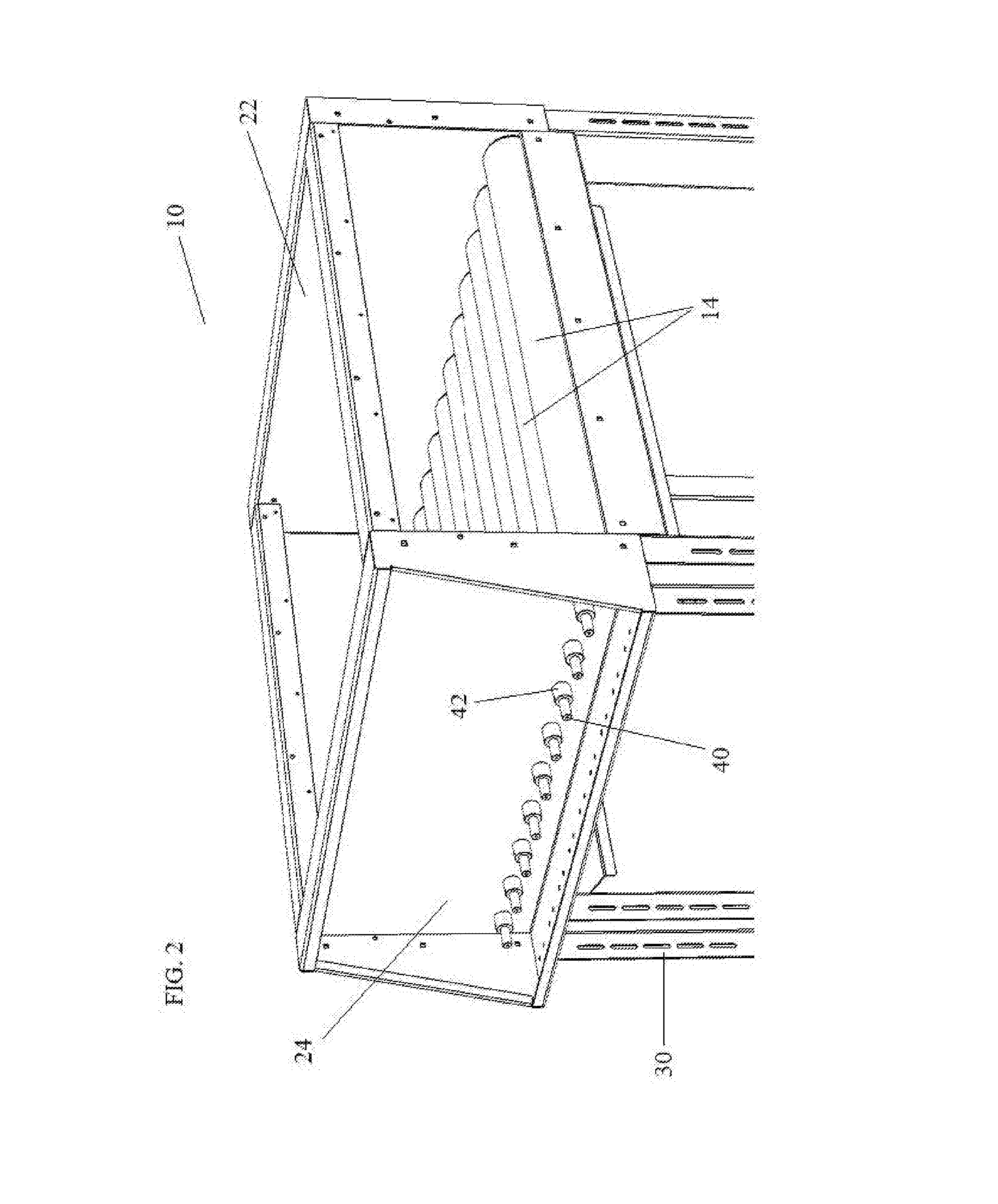
[0066]Referring to the drawings wherein like reference characters designate like or corresponding parts throughout the several views, and referring to FIGS. 1-18, it is seen that the present invention includes various embodiments of a conveyor bed having a magnetic rotor syste...


PUM


Abstract

The present invention provides an improved conveyor system that provides for a magnetically driven conveyor system in which a sidewall of the conveyor may have minimal or no perforations therein for connecting rollers or other conveying structures in the conveyor bed to an external driving mechanism. The conveyor system may also provide gapless or nearly gapless roller bed that prevents or reduces the accumulation of debris and contaminants in and between the hardware of the conveyor bed. The system of the present invention may provide a more efficient and sanitary conveyor system for produce washing or other food processing application that requires less maintenance.

Description

[0001]This application claims the benefit of U.S. Provisional Application No. 62 / 127,197 filed on Mar. 2, 2015, which is incorporated herein by this reference in its entirety.FIELD OF THE INVENTION[0002]The present invention relates to novel conveyor systems, and more particularly to roller conveyor systems employing a magnetic rotor system for rotating the rollers while preventing contamination of the conveyor system, and methods of using the same.DISCUSSION OF THE BACKGROUND[0003]A wide variety of conveyor systems have been developed for use in transporting produce during harvest, cleaning, and packaging. Roller conveyors are commonly used in such applications. Roller conveyors may be used, for example, in produce washing tables, which may include a set of rollers having bristles thereon for contacting the fruit, a retaining wall along the lateral sides of the table to prevent the produce from falling off of the washing table, and a roller driving system that engages the rollers t...

Claims


Application Information

Patent Timeline
Patent Type & Authority Applications(United States)
IPC IPC(8): B65G13/06B65G39/08B65G13/11
CPCB65G13/06B65G39/08B65G13/11B65G13/073B65G19/24B65G39/09
Inventor REED, LORIN
Owner REED LORIN
Learn More