
Control system for hybrid vehicle

Active Publication Date: 2016-09-08
TOYOTA JIDOSHA KK
View PDF30 Cites 9 Cited by
  • Summary
  • Abstract
  • Description
  • Claims
  • Application Information

AI Technical Summary

Benefits of technology

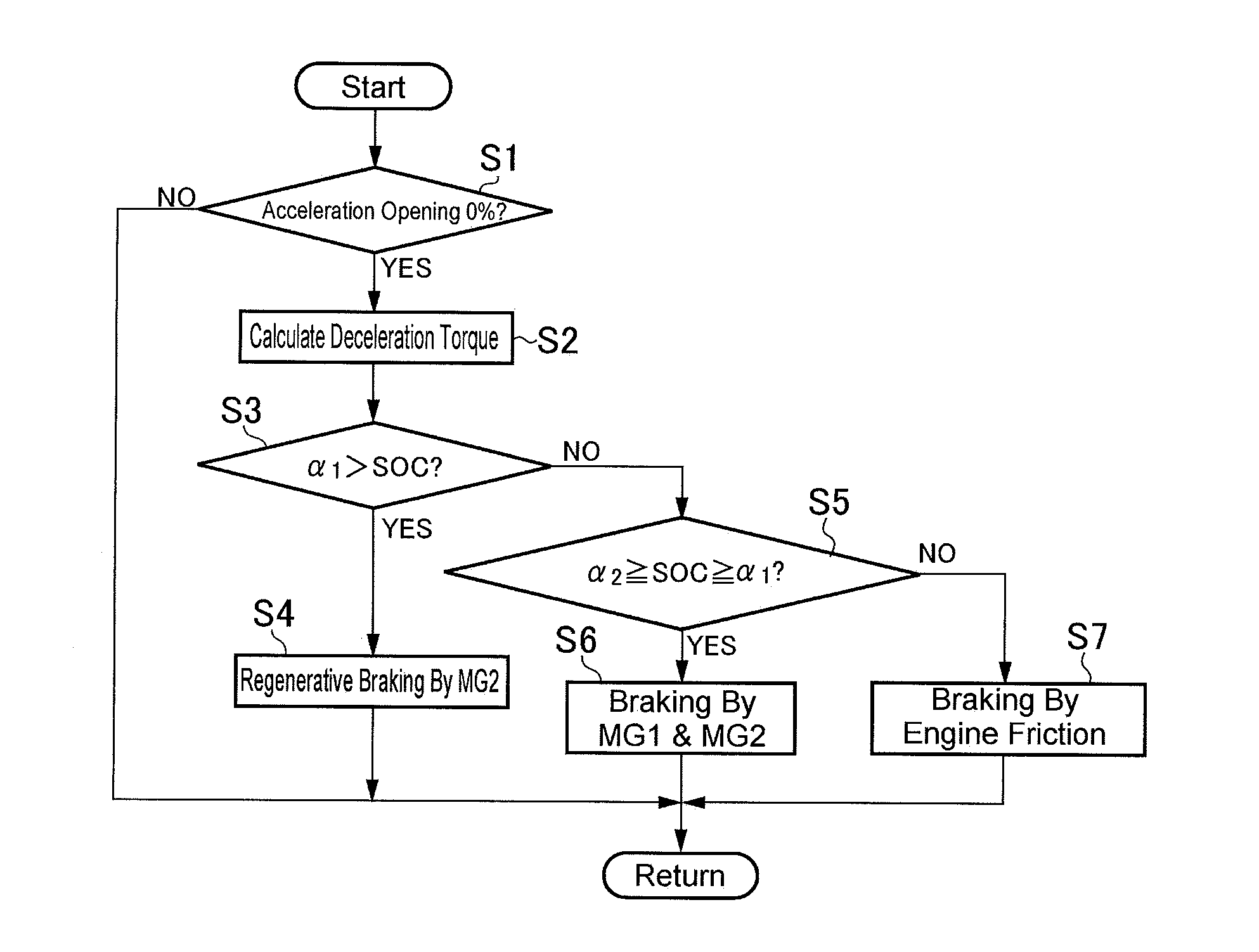
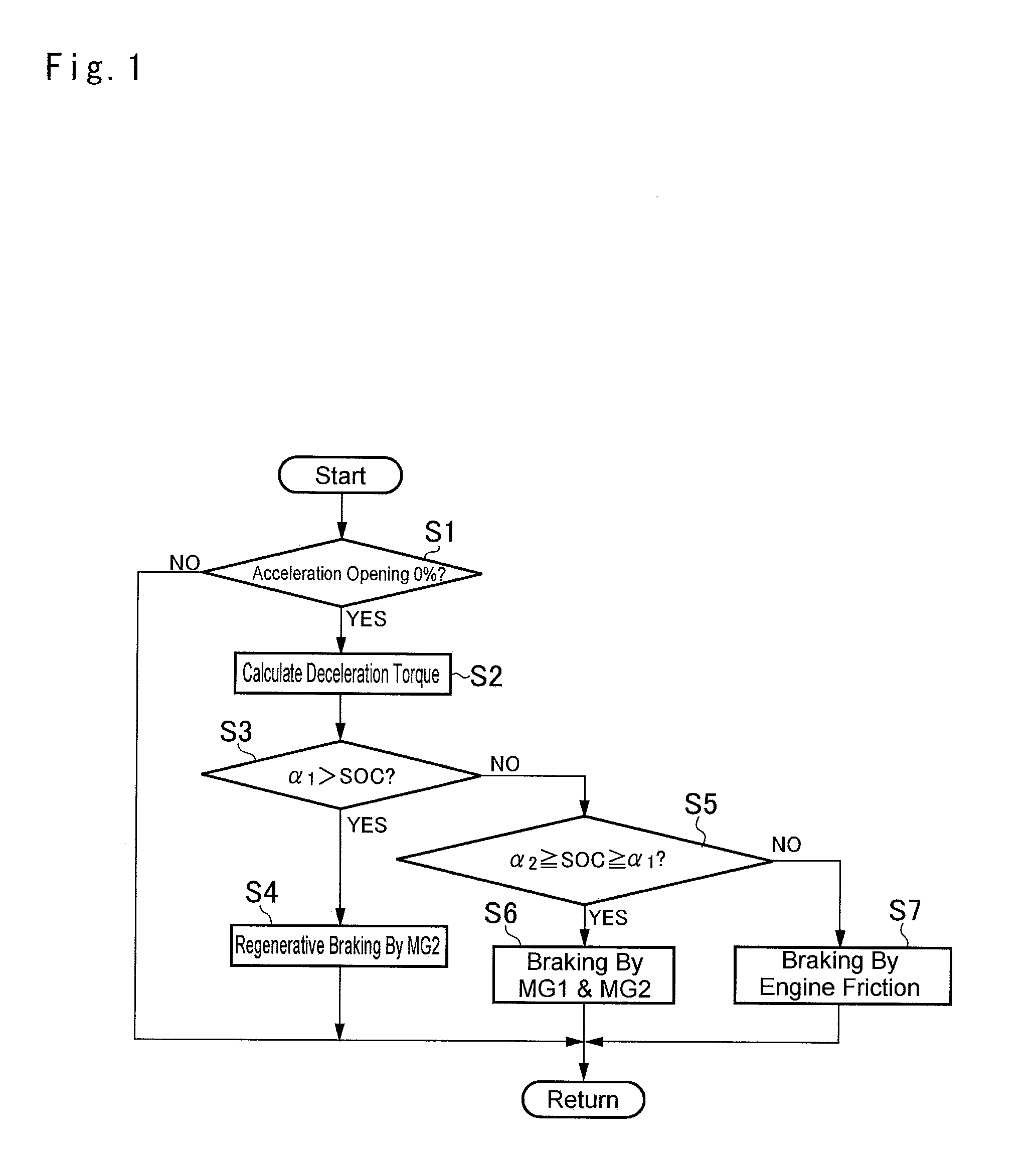
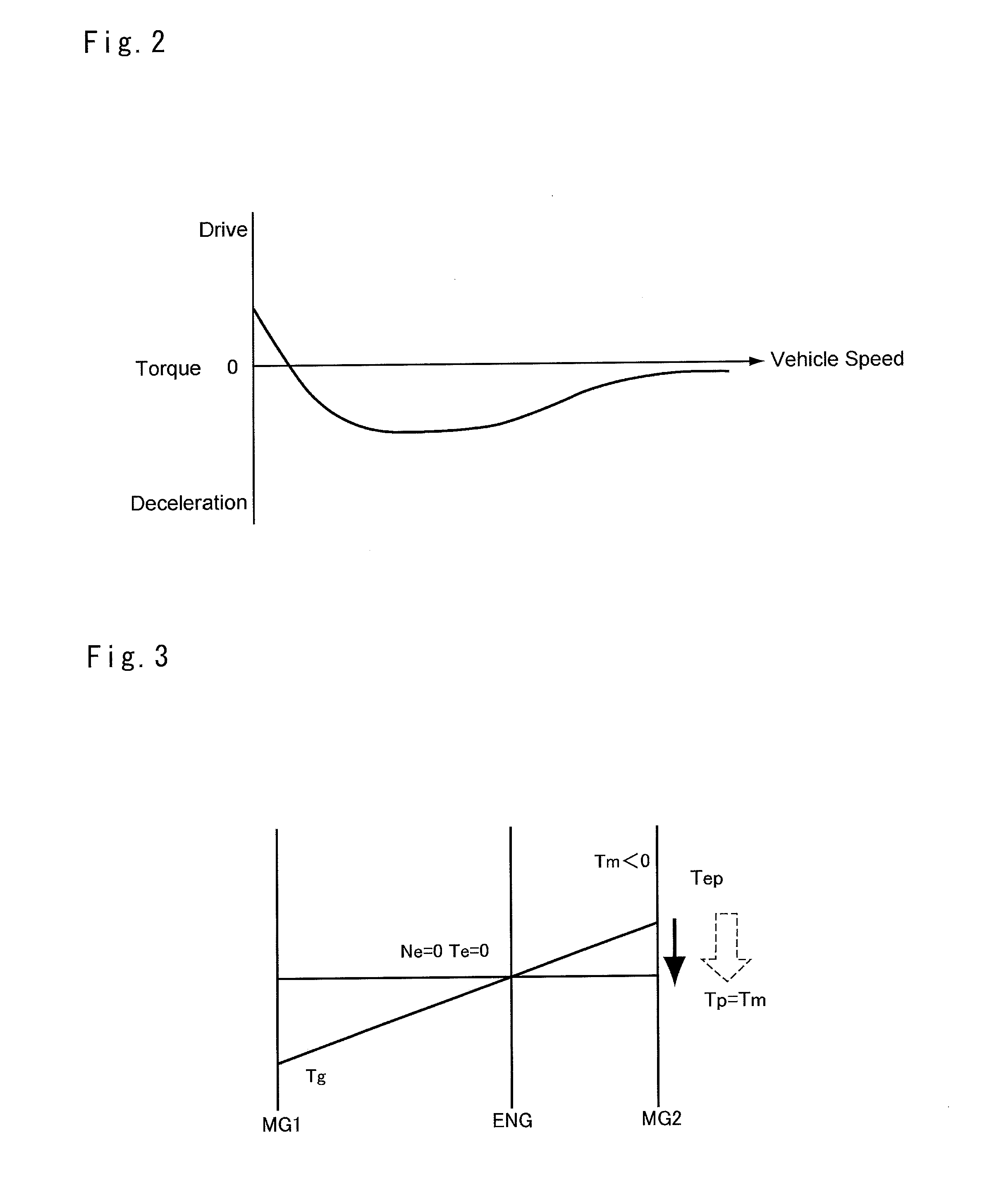
The present invention provides a control system for a hybrid vehicle that reduces discomfort caused by excessive braking. The system uses a second motor as a generator to regenerate energy and establish a deceleration torque, while charging the battery with the generated electric power. This reduces the frequency of rotating the engine and allows for longer periods of regenerative braking, thus reducing discomfort and improving overall efficiency of the vehicle.

Problems solved by technology

In addition, the control system is further configured to consume an electric power generated by the second motor-generator by cranking the engine by the first motor-generator if a battery is charged overly during establishing the braking force by the second motor-generator.
For this reason, the engine is activated frequently and hence a driver may feel discomfort.
In this situation, power circulation is caused between the first motor and the second motor and hence an electrical loss of those motors may also be increased.

Method used


Image

  • Control system for hybrid vehicle
  • Control system for hybrid vehicle
  • Control system for hybrid vehicle

Examples


Embodiment Construction

)

[0023]Preferred example of the present invention will now be explained with reference to the accompanying drawings. Referring now to FIG. 6, there is shown a powertrain of the hybrid vehicle to which the control system according to the preferred example is applied. As illustrated in FIG. 6, the hybrid vehicle comprises an internal combustion engine (as will be simply called the “engine” hereinafter), and a pair of motors individually having a generating function. The hybrid vehicle of this kind may be powered by any one of the motors or both motors while stopping the engine. In the powertrain, specifically, a power distribution device 2 and a first motor 3 are arranged coaxially with the engine 1.

[0024]For example, a gasoline engine and a diesel engine may be used as the engine 1, and the engine 1 is started by compulsory rotating an output shaft 4 thereof (i.e., by a motoring or cranking). The output shaft 4 is connected to a damper device 6 through a clutch 5, and a brake 8 adapt...


PUM


Abstract

A control system for a hybrid vehicle configured to reduce frequency of establishing an engine braking force is provided. The control system is configured to operate a first motor as a motor to increase torque of an output member while halting the output shaft of the engine by a brake, and to increase the deceleration torque of the second motor, if a state of charge of the battery is higher than a predetermined threshold level when deceleration of the hybrid vehicle is demanded.

Description

[0001]The present invention claims the benefit of Japanese Patent Application No. 2015-044521 filed on Mar. 6, 2015 with the Japanese Patent Office, the disclosures of which are incorporated herein by reference in its entirety.BACKGROUND[0002]1. Field of the Invention[0003]Embodiments of the present invention relates to the art of a control system for a hybrid vehicle having different kinds of prime movers such as an internal combustion engine and a motor, and especially to a control system for controlling a braking force established by the prime mover.[0004]2. Discussion of the Related Art[0005]JP-A-2013-129380 describes a hybrid vehicle in which a motor-generator establishes a braking force instead of an engine. The hybrid vehicle taught by JP-A-2013-129380 is provided with the engine, a first motor-generator that can control a speed of the engine, and a second motor-generator that can adjust an output torque. According to the teachings of JP-A-2013-129380, a control system is con...

Claims


Application Information

Patent Timeline
IPC IPC(8): B60W20/14B60L7/10B60L15/20B60L50/16
CPCB60W20/14B60L15/20B60L7/10B60W2710/083Y10S903/947Y10S903/906B60K6/445B60W10/08B60W30/18127B60W20/15B60L7/26B60L15/2009B60L2240/12B60L2240/14B60L2240/423Y02T10/72B60L50/15B60L58/13B60L58/15Y02T10/62Y02T10/64Y02T10/70Y02T10/7072
Inventor OSHIUMI, YASUHIROHIRAI, MAKOTOHOKOI, KOJIAOKI, TAKANORINAKATSUKASA, HIDEO
Owner TOYOTA JIDOSHA KK
Learn More