
Analog and digital dimming control for LED driver

a technology of led driver and led chip, applied in the direction of electroluminescent light source, electric lighting source, semiconductor lamp usage, etc., can solve the problems of high pin count, increased cost, and increased complexity of parts, so as to increase cost, increase the complexity of parts, and increase the pin count

Active Publication Date: 2016-09-01
DIODES INC
View PDF11 Cites 15 Cited by
  • Summary
  • Abstract
  • Description
  • Claims
  • Application Information

AI Technical Summary

Benefits of technology

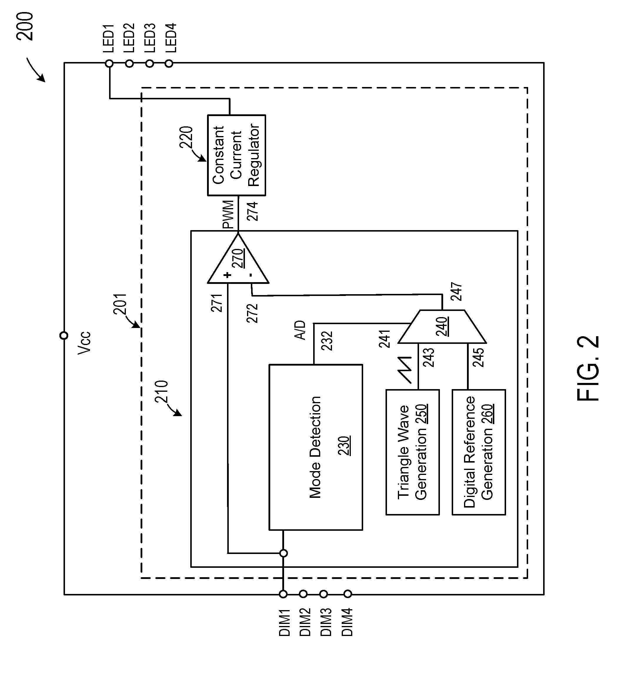
The patent text describes a new LED controller design that solves the problems of conventional controllers by using a single pin to receive both digital and analog dimming signals. This design improves dimming linearity and reduces the complexity and cost of the control circuit and overall LED driver system. It also consumes less chip size and circuit board area, making it ideal for space-limited light bulb systems.

Problems solved by technology

The extra pin count can increase cost, especially for multi-channel LED drivers.
In such applications, high pin count not only increases the complexity of the part, but also consumes more chip size and circuit board area, which is undesirable in a space-limited light bulb system.
A drawback of this approach is that the controller chip tends to be big and consumes more power.
Further, analog dimming regulation does not provide adequate dimming linearity, especially at low current levels, which is desirable for LED lighting systems.

Method used


Image

  • Analog and digital dimming control for LED driver
  • Analog and digital dimming control for LED driver
  • Analog and digital dimming control for LED driver

Examples


Embodiment Construction

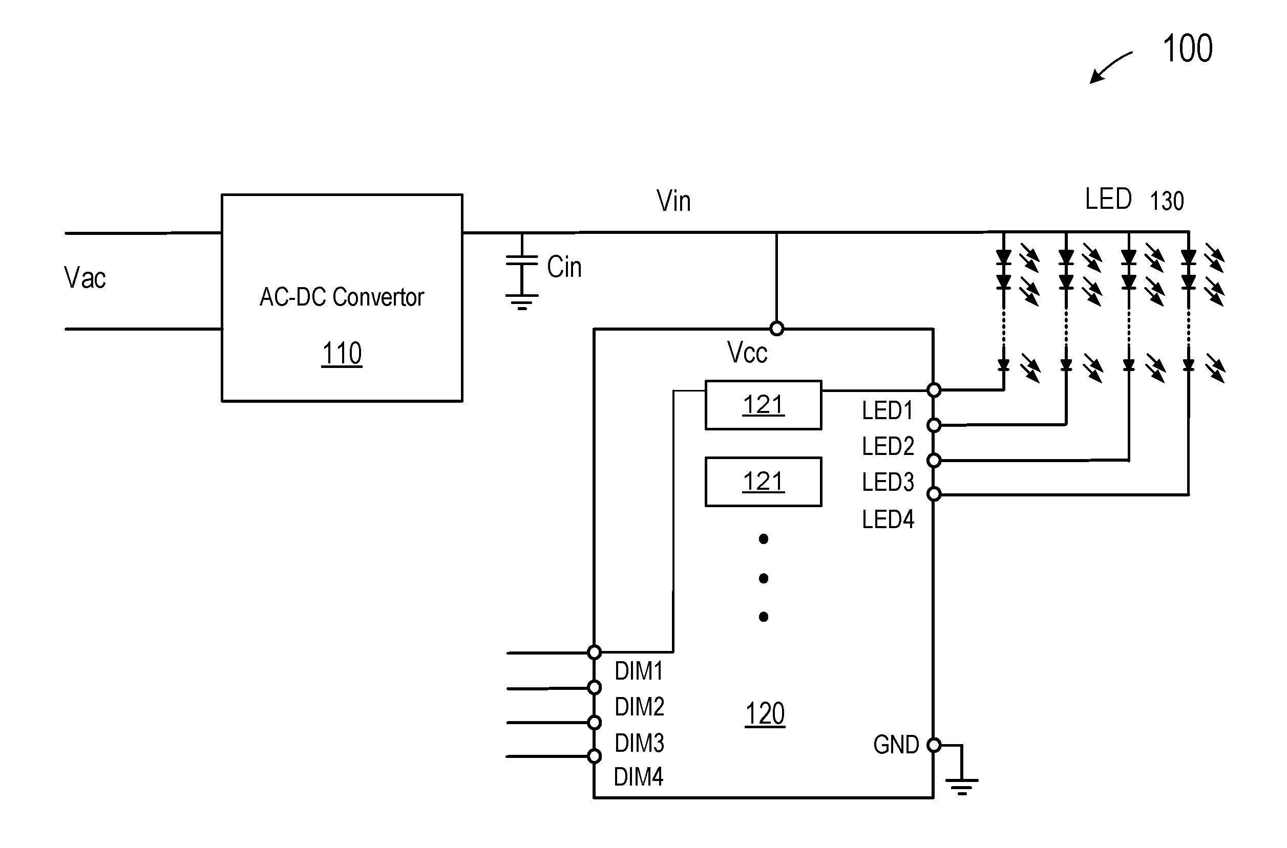
[0028]FIG. 1 is a simplified schematic diagram depicting a power supply for driving an LED (light-emitting-diode) lamp that embodies certain aspects of this invention. As shown in FIG. 1, power supply 100 includes an AC-DC converter 110 coupled to an AC input source Vac for providing a DC voltage source Vin. Power supply 100 also includes a linear regulator 120 with a power terminal Vcc coupled to the DC voltage source for receiving a DC power supply Vin. As shown in FIG. 1, DC power supply Vin is also configured to provide power for an LED lamp 130, which has multiple LED strings. In FIG. 1, Vin is connected to the anodes of the LED strings. However, Vin can also be connected to the cathodes of the LED strings. Linear regulator 120 also includes one or more channels 121 configured to regulate a current flow in the LED string. Linear regulator 120 also has output terminals LED1, . . . , LED4, etc., coupled to LED strings of the LED lamp and input terminals, DIM1, . . . , DIM4, etc.,...


PUM


Abstract

A control circuit includes an input terminal for receiving an input signal, which maybe either a digital input signal or an analog input signal, and the control circuit is configured to provide a digital control signal in response to the input signal. The control circuit may include a mode detection circuit for determining whether the input signal is a digital signal or an analog signal and providing a mode signal, a multiplexer circuit configured to select either a digital reference signal or an analog reference signal in response to the mode signal, and a comparator configured for comparing the input signal with the reference signal selected by the multiplexer to provide the PWM control signal.

Description

CROSS-REFERENCES TO RELATED APPLICATIONS[0001]This application claims priority to U.S. Provisional Patent Application No. 62 / 126,440, filed on Feb. 27, 2015, the content of which is incorporated herein by reference in its entirety.BACKGROUND OF THE INVENTION[0002]Light-emitting diodes (LED) offer many advantages over conventional lighting apparatus, such as long lifetime, high efficiency, and non-toxic materials. With the development of electronic technology, light-emitting diodes are finding ever wider applications. For example, in consumer applications, LED light bulbs are showing promise as replacement for conventional white light incandescent or florescent light bulbs. Further, more and more electronic devices adopt LCD as display, and LEDs are becoming increasingly popular as a backlight source.[0003]LEDs are generally regulated by controlling their current. Typically, LEDs are operated such that their average current is constant, and power electronics components are used to cr...

Claims


Application Information

Patent Timeline
IPC IPC(8): H05B33/08H05B44/00
CPCH05B33/0812H05B33/0845H05B45/395H05B45/10H05B45/44Y02B20/30
Inventor WANG, ADRIANSU, CHEIN-JENSHIH, WELTON
Owner DIODES INC
Learn More