Segment conductors, stator, rotating electrical machine, and vehicle and method of manufacturing the segment conductors

a technology of segment conductors and manufacturing methods, which is applied in the direction of dynamo-electric machines, electrical devices, windings, etc., can solve the problems of internal stresses and strains at bent parts, cracking or bulging, etc., and achieves small internal stress and small electric resistance. , the effect of small internal stress

Inactive Publication Date: 2016-09-01
COPAL CO LTD
View PDF2 Cites 10 Cited by
  • Summary
  • Abstract
  • Description
  • Claims
  • Application Information

AI Technical Summary

Benefits of technology

The invention provides a segment conductor that is resistant to cracking and has low internal stress. The manufacturing method allows for easy production of a thin segment conductor with low internal stress. The invention also results in a segment conductor with low electric resistance and low height of the exposed coil end portion.

Problems solved by technology

Moreover, when U-shaped conductors are formed through a bending process on rectangular copper wires that are thick and that have a large cross-sectional area, for example, this produces internal stresses and strains at the bent parts.
Moreover, when the pair of legs portions of a U-shaped conductor are twisted and opened up, in order to insert to the U-shaped conductor into a slot in a stator core, this may produce faults such as cracking or bulging, through large internal stresses, large strains, embrittlement, or the like, at the bent portions.

Method used


Image

  • Segment conductors, stator, rotating electrical machine, and vehicle and method of manufacturing the segment conductors
  • Segment conductors, stator, rotating electrical machine, and vehicle and method of manufacturing the segment conductors
  • Segment conductors, stator, rotating electrical machine, and vehicle and method of manufacturing the segment conductors

Examples


Embodiment Construction

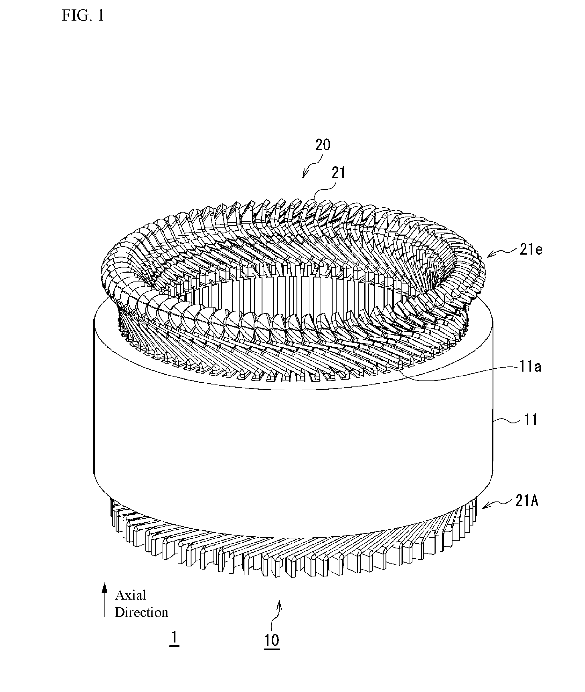
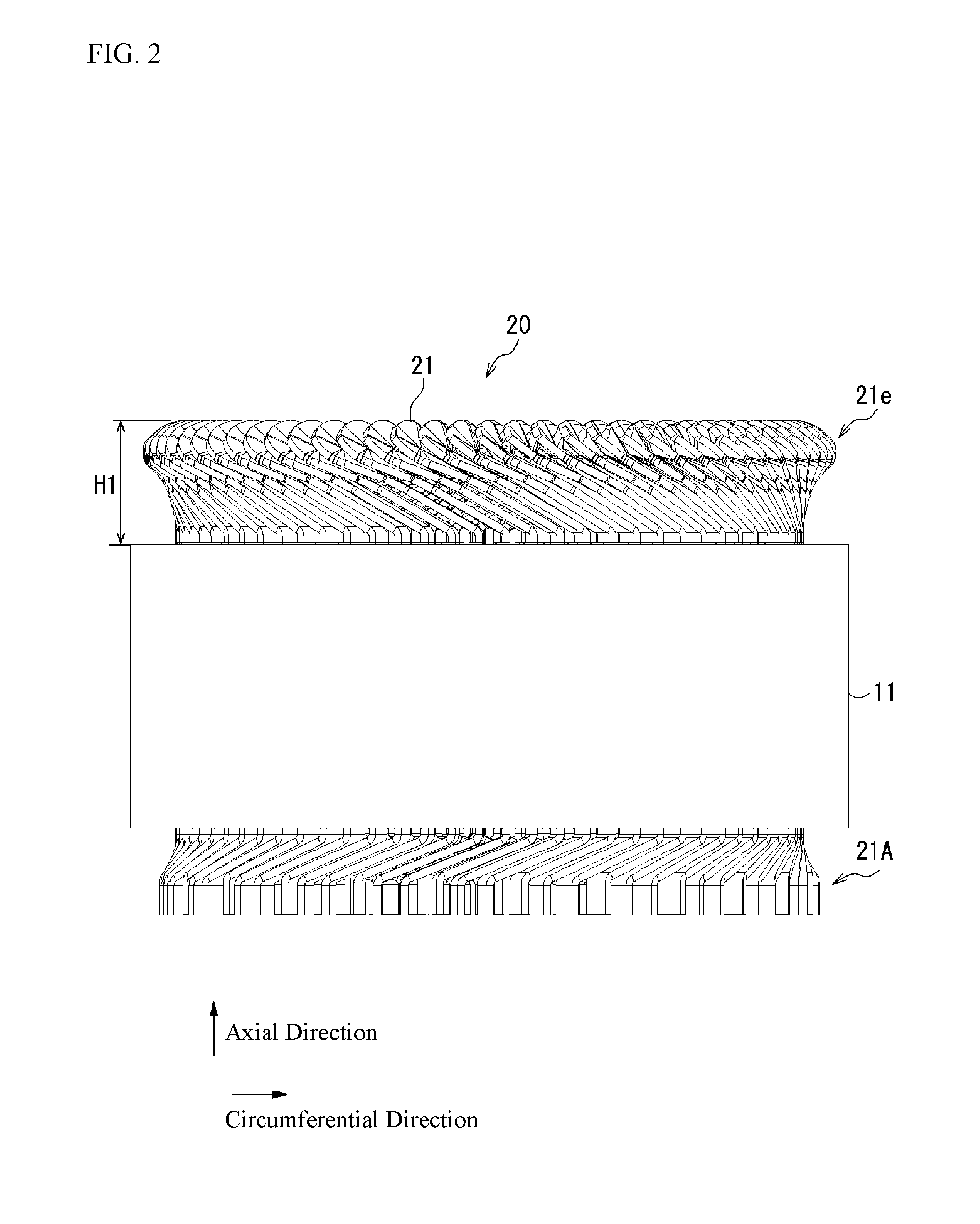
[0050]A segment conductor (a divided lead wire) according to an example according to the present invention is a conductive element of a coil that is wired through distributed winding in a stator core of a rotating electric machine. The segment conductor is formed through press forming, and is provided with a pair of straight conductor portions and a bent conductor portion that connects together one end side of the pair of straight conductor portions. The stator of the rotating electric machine has a structure wherein a plurality of segment conductors are arranged, through distributed winding, in a stator core. Moreover, a vehicle is equipped with this rotating electric machine.

[0051]The segment conductor has a rectangular cross-section, and is provided with a pair of straight conductor portions and a bent conductor portion that connects together one end side of the pair of straight conductor portions, where the cross-sectional thickness of the part of the bent conductor portion that...


PUM


Abstract

A segment conductor that is a conductive element of a coil wound in a distributed winding in a stator core of a rotating electric machine is formed, through press forming and is provided with a pair of straight conductor portions and a bent conductor portion that connects together one end side of the pair of straight conductor portions. Moreover, one part of the segment conductor is formed, through press forming, so as to be thinner than another part. Specifically, a part that is exposed from the stator core is formed, through press forming, so as to be thinner than a part that is contained in a slot of the stator core. The stator has a structure wherein a plurality of segment conductors are disposed in a distributed winding in the stator core. The rotating electric machine is equipped with this stator. The vehicle is equipped with this rotating electric machine.

Description

CROSS-REFERENCE TO RELATED APPLICATIONS[0001]The present application claims priority to Japanese Patent Application Nos. 2015-037337, filed Feb. 26, 2015, 2015-037338, filed Feb. 26, 2015, and 2015-120936, filed Jun. 16, 2015. These applications are incorporated herein by reference in their entirety.FIELD OF TECHNOLOGY[0002]The present invention relates to a segment conductor, a stator, a rotating electric machine, a vehicle, and a manufacturing method for segment conductor.BACKGROUND[0003]There are known needle-shaped conductor sequentially connected coils for rotating electric machines formed through inserting needle-shaped conductors (essentially U-shaped conductors), from the front side, into each of a plurality of slots formed in a stator core of a round cylindrical shape, and sequentially connecting the tip ends of the individual needle-shaped conductors, which protrude to the rear side of the stator core, to tip ends of other needle-shaped conductors (referencing, for example...

Claims


Application Information

Patent Timeline
Patent Type & Authority Applications(United States)
IPC IPC(8): H02K3/28H02K15/04
CPCH02K15/04H02K3/28H02K3/04H02K3/50H02K15/0421H02K2213/03H02K3/12
Inventor WATANABE, MASAKAZUFUKASAKU, YOSHINORIIWASE, MASATOKUNII, KOKINAGASAWA, HIROFUMIKOIKE, SHINJI
Owner COPAL CO LTD
Why Eureka
Try Eureka