
Apparatus for connection of thermoplastic tubing

a technology of thermoplastic tubing and apparatus, which is applied in the direction of tube connectors, other domestic objects, medical devices, etc., can solve the problems of several separate welders, time-consuming and labor-intensive maintenance, and difficult and costly validation

Active Publication Date: 2016-09-01
CYTIVA SWEDEN AB
View PDF0 Cites 4 Cited by
  • Summary
  • Abstract
  • Description
  • Claims
  • Application Information

AI Technical Summary

Benefits of technology

The patent text describes an invention that allows for the proper alignment and joining of different thermoplastic tubing sizes through welding. The apparatus can accommodate tubing of different diameters and securely clamp them without over-compression, resulting in strong and leak-free joints. The technical effect of this invention is that it allows for a reliable and efficient method for joining thermoplastic tubing, regardless of their size, in a safe and aseptic manner.

Problems solved by technology

However, maintaining a clean room is time consuming, difficult and costly to validate
These connections are simple, repeatable and validatable but they normally have to be applied during manufacture of the sets and are not amenable to the setting up of tailor-made systems directly in the bioprocess facility.
It is also quite commonly used in bioprocess settings, although a drawback of the available technology is that several separate welders have to be used for tubing of different diameters which are often used simultaneously in different parts of a single bioprocess to accommodate ranges of flow-rates, pressures etc.

Method used


Image

  • Apparatus for connection of thermoplastic tubing
  • Apparatus for connection of thermoplastic tubing
  • Apparatus for connection of thermoplastic tubing

Examples


Embodiment Construction

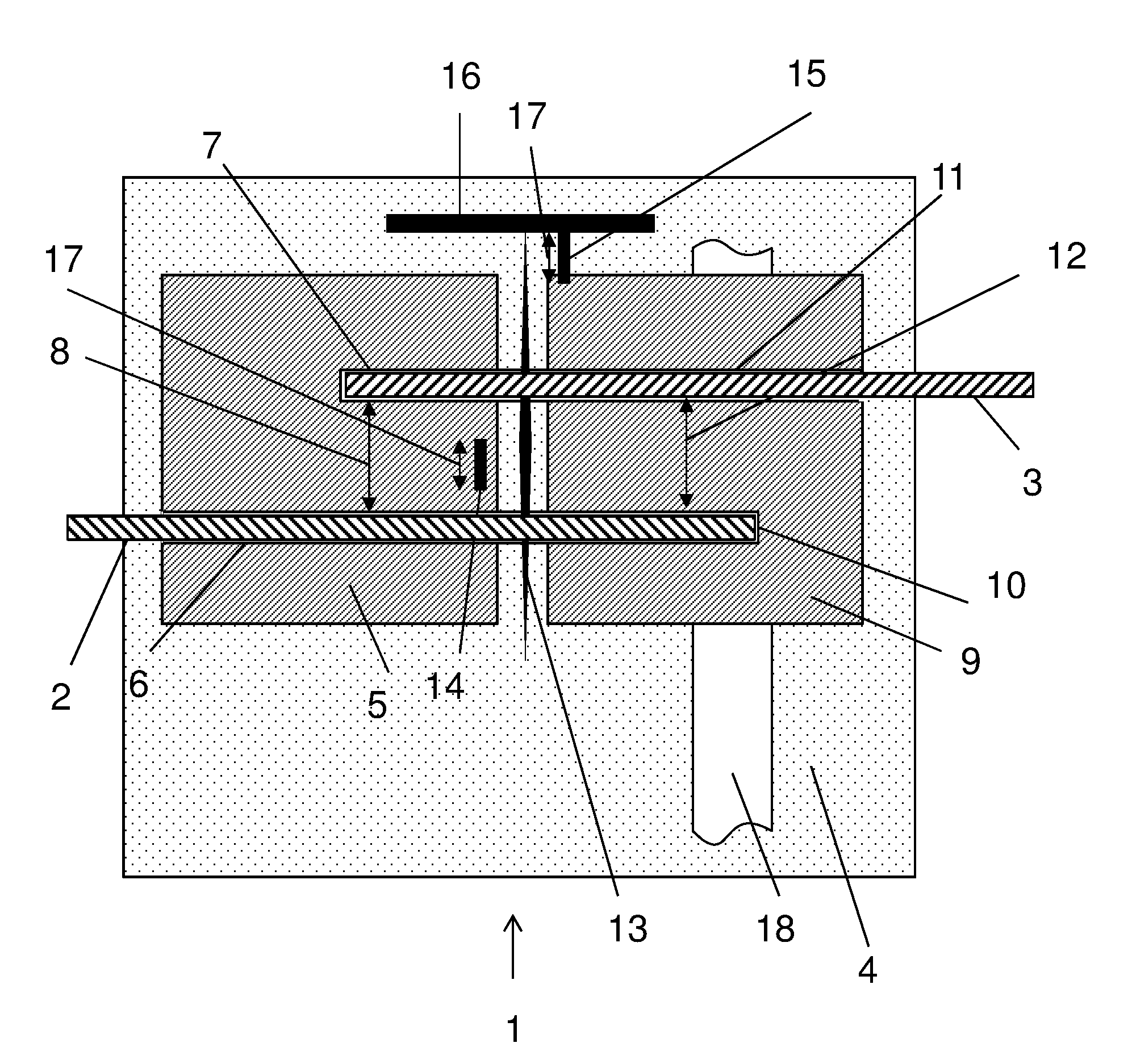
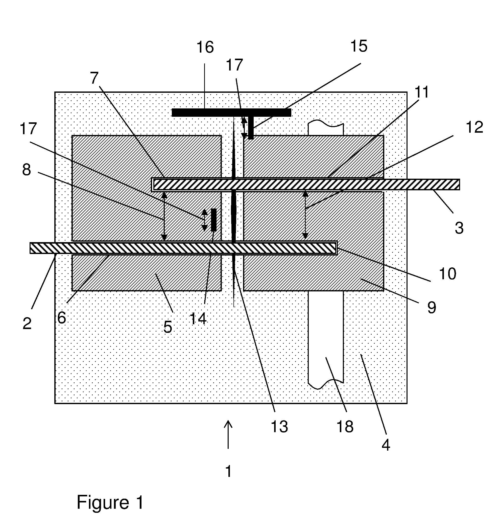
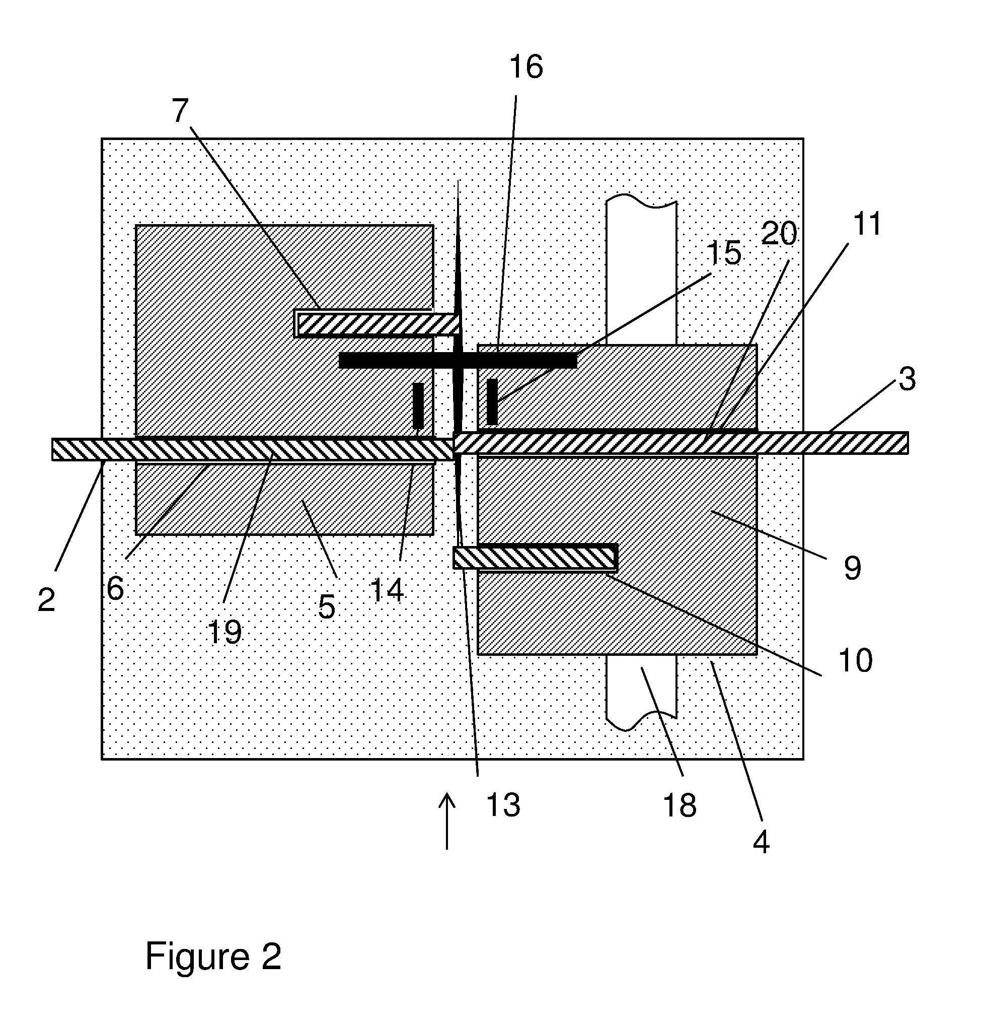
[0022]In one aspect, as illustrated by FIGS. 1-8, the present invention discloses an apparatus 1;101 for aligning and supporting a first 2;102 and a second 3;103 length of thermoplastic tubing, preparatory to and during cutting and welding of the lengths of tubing. Suitably, both lengths of tubing have the same diameter. The apparatus comprises the following components arranged on a base support 4:

[0023]a) a first holder 5;105 arranged to accommodate portions of the first 2;102 and second 3;103 lengths of tubing in a first 6;106 and a second 7;107 elongated holding space respectively, wherein the two holding spaces are essentially parallel to each other and separated from each other by a first distance 8;108. The length axes of the two holding spaces can be arranged at an angle of less than 5 degrees, such as less than 2 degrees or less than 1 degree towards each other.

[0024]b) a second holder 9;109 arranged to accommodate (other) portions of the first 2;102 and second 3;103 lengths...


PUM

PropertyMeasurementUnit
outer diametersaaaaaaaaaa

Abstract

The invention discloses an apparatus (1) for aligning and supporting a first (2) and a second (3) length of thermoplastic tubing, preparatory to and during cutting and welding of said lengths of tubing, where the apparatus comprises the following components arranged on a base support (4):a) a first holder (5) arranged to accommodate portions of the first and second lengths of tubing in a first (6) and a second (7) elongated holding space respectively, wherein the holding spaces are essentially parallel to each other and separated from each other by a first distance (8);b) a second holder (9) arranged to accommodate portions of the first and second lengths of tubing in a third (10) and a fourth (11) elongated holding space respectively, wherein the holding spaces are essentially parallel to each other and to the holding spaces in the first holder and separated from each other by a second distance (12) substantially the same as the first distance (8), and wherein said second holder is movable in a direction essentially perpendicular to the holding spaces of the first and second holders from a cutting position where said first holding space (6) is aligned with said third holding space (10) and said second holding space (7) is aligned with said fourth holding space (11) to a welding position where said first holding space (6) is aligned with said fourth holding space (11);c) cutting means (13) arranged between said first and second holders for cutting said lengths of tubing when the second holder is in the cutting position;d) aligning means arranged to abut the outside of a cut length of tubing accommodated in the first holding space (6) and the outside of a cut length of tubing accommodated in the fourth holding space (11) and to align these lengths of tubing with each other.

Description

TECHNICAL FIELD OF THE INVENTION[0001]The present invention relates to sterile connection of thermoplastic tubing, and more particularly to an apparatus for sterile connection by welding. The invention also relates to a method of sterile connection of thermoplastic tubing by welding.BACKGROUND OF THE INVENTION[0002]The biotechnology industry uses different manufacturing systems for creating aseptic and sterile connections between process containers and equipment, such as plastic bags and pumps. A known manufacturing system uses controlled environments such as clean rooms or cabinets to ensure aseptic connections during manufacture. When necessary connections are made in such a controlled environment that breaches sterile tubing and piping, the environment does not contaminate the fluid flow passage. However, maintaining a clean room is time consuming, difficult and costly to validate[0003]For example separation or reaction systems such as chromatography systems, filter systems or bi...

Claims


Application Information

Patent Timeline
Patent Type & Authority Applications(United States)
IPC IPC(8): B29C65/78B29C65/20B29C65/00B29C65/74
CPCB29C65/7802B29C65/74B29C65/2046B29C66/1142B29L2031/753B29C66/73921B29C65/1412B29C65/16B29C65/103B29C66/857A61M39/14A61M39/18B29C66/5221B29C66/71B29C65/7841B29L2023/007B29C66/8414B29C66/0018B29K2021/003B29K2027/06A61M39/146
Inventor CHENGALVARAYAN, KISHORERAMAKRISHNA, MANOJ
Owner CYTIVA SWEDEN AB
Learn More