LED backlight driving circuit and method for detecting failure thereof

Active Publication Date: 2016-08-25
TCL CHINA STAR OPTOELECTRONICS TECH CO LTD
View PDF14 Cites 4 Cited by
  • Summary
  • Abstract
  • Description
  • Claims
  • Application Information

AI Technical Summary

Benefits of technology

The present disclosure provides an LED backlight driving circuit with a detection unit that can accurately detect failure of the circuit. In the testing mode, the detection unit supplies a variable testing voltage to the driving chip, which leads to a gradual decrease in current flowing through the LED light strip. This results in an increase in voltage on the negative end of the LED light strip, allowing for the accurate detection of short circuits or virtual-off states of the LED light strip. In summary, this disclosure provides an improved LED backlight driving circuit with advanced detection capabilities.

Problems solved by technology

However, the inventor found through repeated observations that the above driving chip often provides wrong judgments in practice.
Or, if an LED light strip fails, but a voltage on its negative end is not higher than the threshold voltage, the driving chip will not activate the protection function.
In particular, if there is only one LED light in an LED light strip that is short-circuited or virtually off, it will be very difficult for the driving chip to identify the failure because the voltage on its negative end will not vary much and will not be higher than the threshold voltage.
In addition, due to the obstruction of fittings such as the light guide plate and films disposed within the backlight module, it will also be difficult to detect the failure manually.
Thus, the circuit abnormity will continue to be present and become worse, thereby causing safety problems.

Method used


Image

  • LED backlight driving circuit and method for detecting failure thereof
  • LED backlight driving circuit and method for detecting failure thereof
  • LED backlight driving circuit and method for detecting failure thereof

Examples


Embodiment Construction

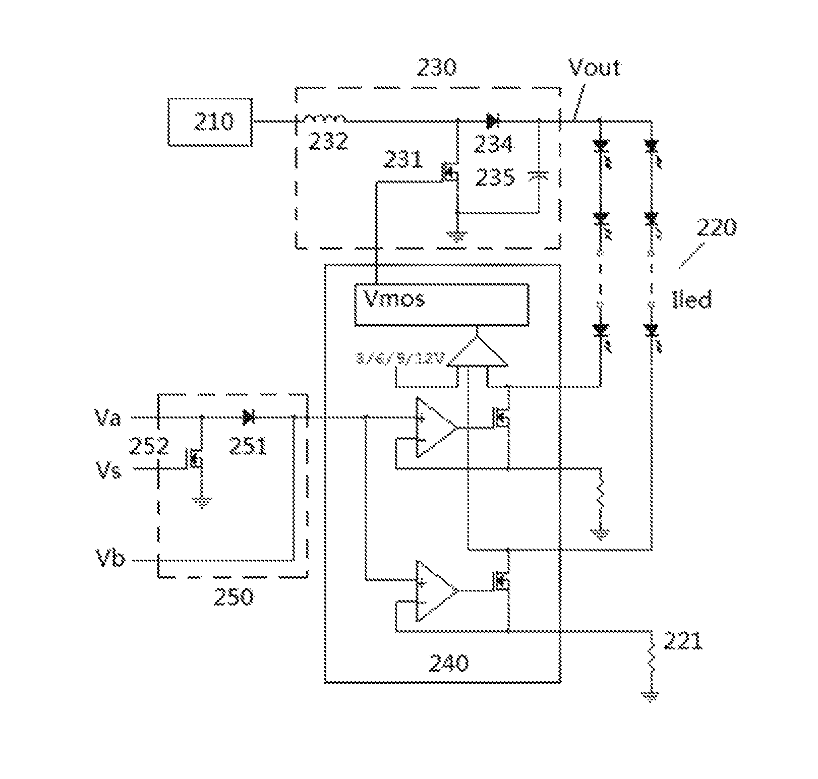
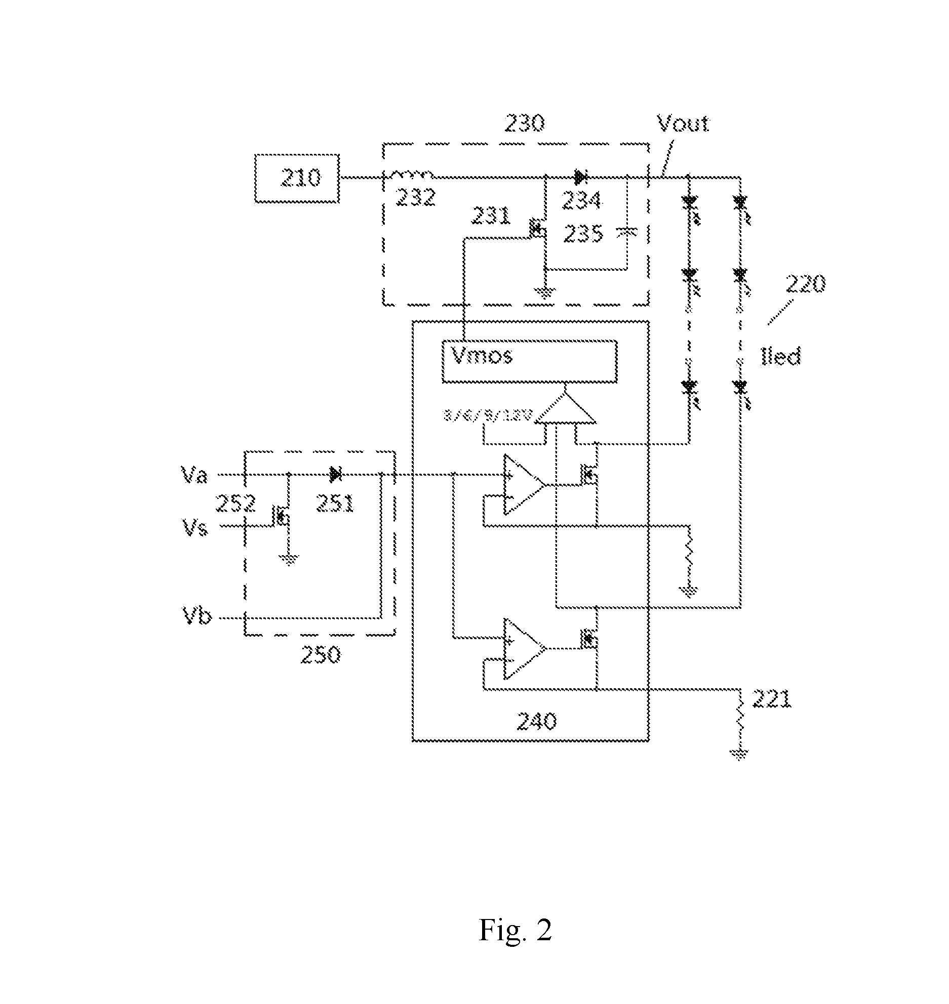
[0028]As shown in FIG. 2, to solve the above technical problem, according to the present disclosure improvements are proposed on the existing LED backlight driving circuit. It can be seen from FIG. 2 that the LED backlight driving circuit provided by the present disclosure comprises: a power supply unit 210; a plurality of LED light strips 220; a booster unit 230 which is electrically connected between the power supply unit 210 and the plurality of LED light strips 220; a driving chip 240 which is electrically connected between the plurality of LED light strips 220 and the booster unit 230; as well as a detection unit 250 which is electrically connected to the driving chip 240. The detection unit 250 is able to supply a fixed operating voltage Va to the driving chip 240 in a normal mode, and supply a variable testing voltage Vb to the driving chip 240 in a testing mode.

[0029]A detailed description will be provided below to the specific arrangement of each of the above functional uni...


PUM


Abstract

Disclosed is an LED backlight driving circuit and method for detecting failure thereof. A driving chip of the circuit, on the one hand, is electrically connected to a control end of a booster unit so as to transmit a gate control signal to the booster unit, for regulating a driving voltage supplied by a power supply unit to an LED light strip through the booster unit, and on the other, is electrically connected between an output end of a detection unit and a negative end of the LED light strip, forming a current path of the LED light strip. When the detection unit outputs a variable testing voltage, the driving chip controls a current flowing through the LED light strip so that the current changes with the testing voltage, and judges whether to cut off its electrical connection to the LED light strip based on a comparison of a voltage on the negative end of the LED light strip and a predetermined threshold voltage.

Description

CROSS-REFERENCE TO RELATED APPLICATIONS[0001]The present application claims benefit of Chinese patent application CN201410557591.2, entitled “LED backlight driving circuit and method for detecting failure thereof” and filed on Oct. 20, 2014, the entirety of which is incorporated herein by reference.TECHNICAL FIELD[0002]The present disclosure relates to backlight driving technologies of display panels, and in particular, to an LED backlight driving circuit and a method for detecting failure thereof.TECHNICAL BACKGROUND[0003]In the existing image display technologies, TFT liquid crystal display devices have distinguished themselves in virtue of their excellent properties, and have been widely used in various areas such as cell phones, computers, televisions, etc. Liquid crystal display devices achieve display of images by controlling transmittance of backlight source through causing non-luminous liquid crystal to deflect under the influence of voltage, and therefore, backlight module ...

Claims


Application Information

Patent Timeline
IPC IPC(8): H05B33/08G09G3/34H05B44/00
CPCG09G3/36G09G3/3406H05B33/0893H05B33/0827H05B33/0845H05B33/0815G09G2330/04G09G2330/12H05B45/58H05B45/38H05B45/10H05B45/46
Inventor ZHANG, HUA
Owner TCL CHINA STAR OPTOELECTRONICS TECH CO LTD
Why Eureka
Try Eureka