
Drive Unit for Image Capturing Device and Control Method Thereof

a technology of image capture device and drive unit, which is applied in the direction of color television details, television system details, television systems, etc., can solve the problems of excessive mechanical motion appearance, large motor size and thus heavy, etc., and achieve the effect of reducing parts cost, reducing weight, and reducing generated nois

Active Publication Date: 2016-08-25
GODLER IVAN
View PDF0 Cites 5 Cited by
  • Summary
  • Abstract
  • Description
  • Claims
  • Application Information

AI Technical Summary

Benefits of technology

The invention is a drive unit that uses less weight, less noise, and fewer parts. It achieves a wide range of motion performances, from precise positioning to fast motion. The drive unit includes a control unit that can rotate at a maximum speed of 900 angular degrees per second, which is similar to the speed of a human eye.

Problems solved by technology

A large torque is needed to realize fast motion, therefore, in the case of directly coupled motors, the motors become large and thus heavy.
On the other hand, in the case of gear reducers used with the motor, the weight and size of the motors can be reduced, but the mechanisms generate noise, and the motion appearance is “too mechanical” to be suitable for humanoid robots, which should resemble eye motion of a live being.

Method used


Image

  • Drive Unit for Image Capturing Device and Control Method Thereof
  • Drive Unit for Image Capturing Device and Control Method Thereof
  • Drive Unit for Image Capturing Device and Control Method Thereof

Examples


Embodiment Construction

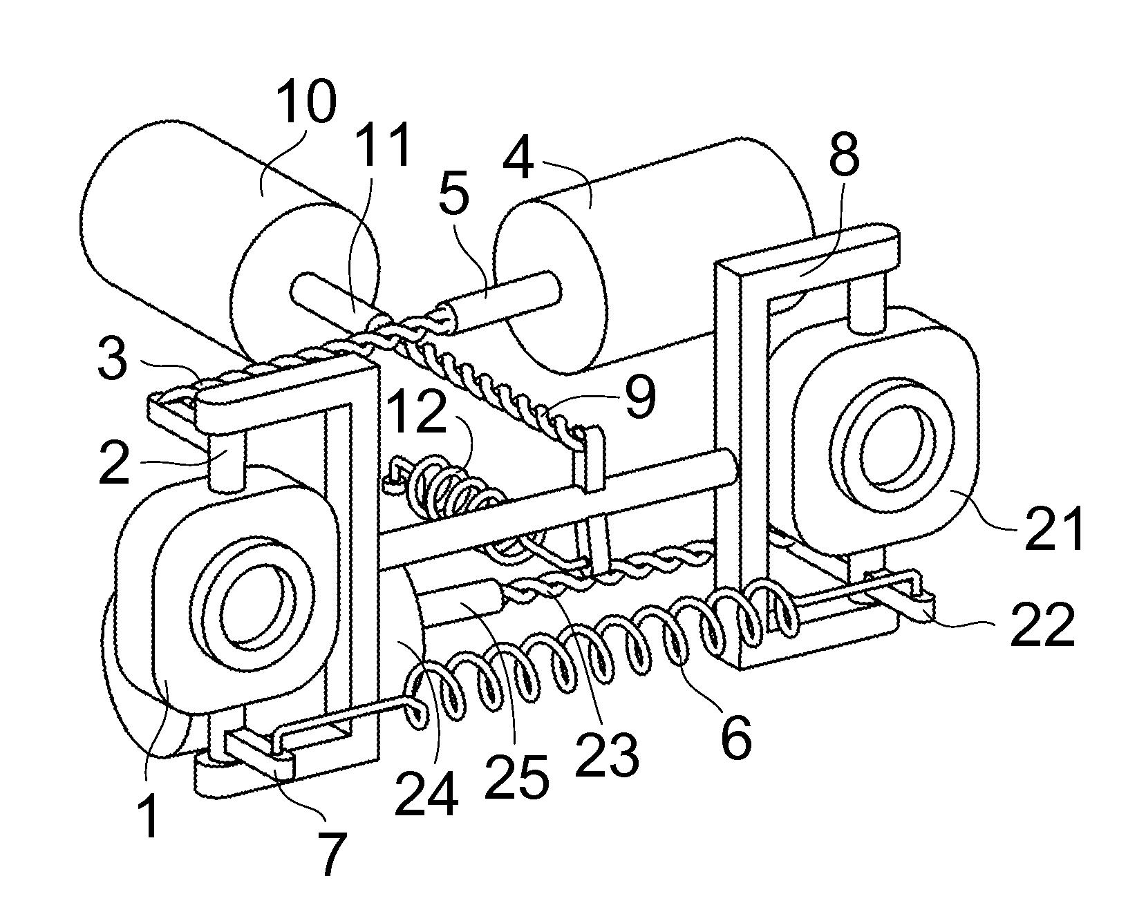
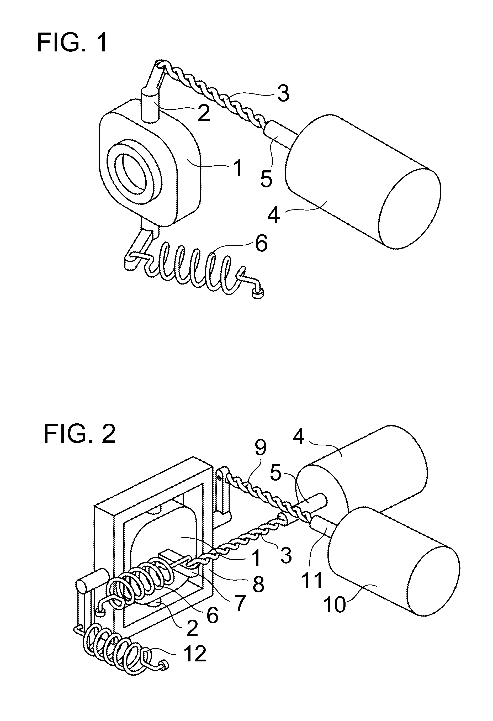
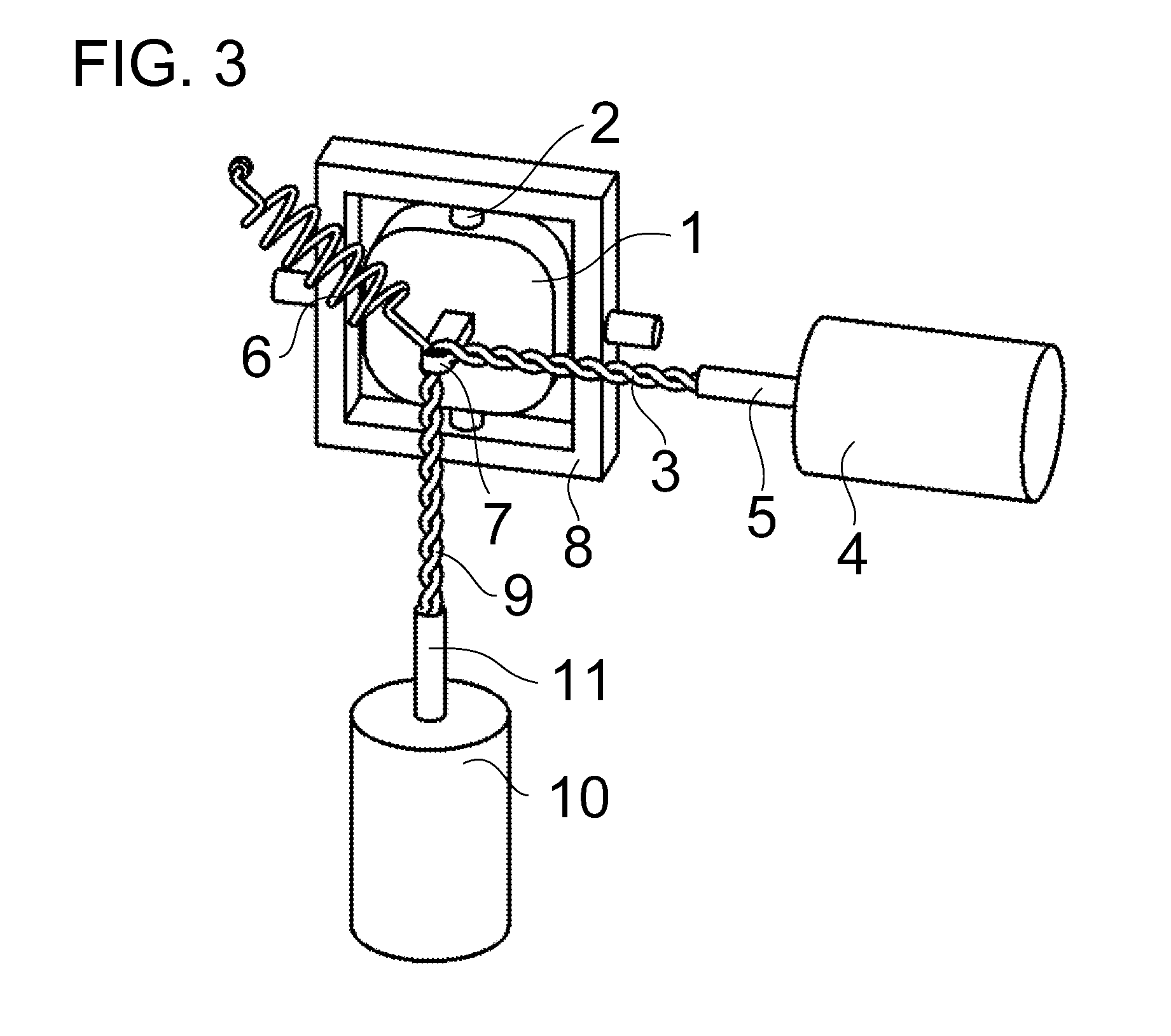
[0023]FIG. 1 shows an isometric view of a drive unit where two or more strings 3 are with one end attached to a shaft 5 of a driving motor 4, and with the other end are coupled to a member 2, which is fixed to the image capturing device 1, and supports the image capturing device 1 so that it can rotate around its vertical axis. Rotation of the shaft 5 twists the strings 3 and thus generates a pulling force on the member 2, which rotates together with the image capturing device 1 around its vertical axis. A spring 6 is directly or indirectly attached to the image capturing device 1 in such a way that generates a motion of the image capturing device 1 in opposite direction to the pulling direction of the twisted strings 3. The twisted strings 3 and the spring 6 thus operate as an antagonistic pair on the image capturing device 1, with a function to rotate the image capturing device 1 around its vertical axis in both directions.

[0024]FIG. 2 shows an image capturing device 1 attached by...


PUM


Abstract

Drive unit that consists of two or more strings that are with one end attached to a shaft of a driving motor, and with the other end directly or indirectly coupled to an image capturing device, which is supported by means that allow rotation is disclosed. The twisting strings produce a pulling force on the ends of the strings, which generates a motion of the image capturing device. The invented drive unit does not use gears, belts, pulleys or the like, which reduces the weight, lowers the generated noise, and reduces the parts costs. The invented drive unit including the control unit achieves wide range of motion performances ranging from precise positioning to fast motion, including performance equivalent to a human eye.

Description

CROSS-REFERENCE TO RELATED APPLICATIONS[0001]Japanese patent application: appl. (21) JP 2014-032653 (Feb. 24, 2014)BACKGROUND OF THE INVENTION[0002](1) Field of the Invention[0003]The present invention relates to drive units for image capturing devices and control method thereof. The invented drive unit generates motion of the image capturing device or multiple image capturing devices by using twisted strings mechanism.[0004](2) Description of Related Art[0005]Image capturing devices such as semiconductor cameras are used for surveillance and for robotic eyes, particularly in humanoid robots. Image capturing devices are immovably fixed to the base or are movable with the goal to increase visibility range of the device. Motion of the device can be generated by various types of motors that are directly coupled to the device (for example U.S. Pat. No. 6,628,338 B1) or coupled by gear and / or link mechanisms (for example U.S. Pat. No. 7,777,810 B2).[0006]Particularly in the case of robot...

Claims


Application Information

Patent Timeline
Patent Type & Authority Applications(United States)
IPC IPC(8): H04N5/225H04N5/247H04N23/90
CPCH04N5/247H04N5/2253H04N23/54H04N23/58H04N23/687H04N23/90
Inventor GODLER, IVANSATO, YASUOMIMIYAMOTO, HIROYUKI
Owner GODLER IVAN
Learn More