Liquid ejecting apparatus

Active Publication Date: 2016-08-25
SEIKO EPSON CORP
View PDF3 Cites 6 Cited by
  • Summary
  • Abstract
  • Description
  • Claims
  • Application Information

AI Technical Summary

Benefits of technology

The invention provides a liquid epaying apparatus that can manage its liquid ejecting unit efficiently without nozzles. This is useful for maintaining the unit's performance over a long period of time.

Problems solved by technology

However, the meniscus (curved liquid surface) formed inside the nozzle may collapse, and the ejection capacity of the nozzle may be lowered when droplets of the cleaning solution enter into a nozzle which is not clogged.
In this way, because the results of the maintenance vary according to the state of the nozzle in a case of performing maintenance of the liquid ejecting unit having nozzles with the droplets, a problem arises of the efficiency of the maintenance being poor.
Such a problem is not limited to printers that perform printing while ejecting ink, and is generally common in liquid ejecting apparatuses having nozzles for ejecting liquids.
Meanwhile, in a case where a heavy degree of clogging occurs in the nozzle, it is difficult to resolve the clogging with the energy for ejecting the droplets of the first liquid from the nozzle.

Method used


Image

  • Liquid ejecting apparatus
  • Liquid ejecting apparatus
  • Liquid ejecting apparatus

Examples


first example

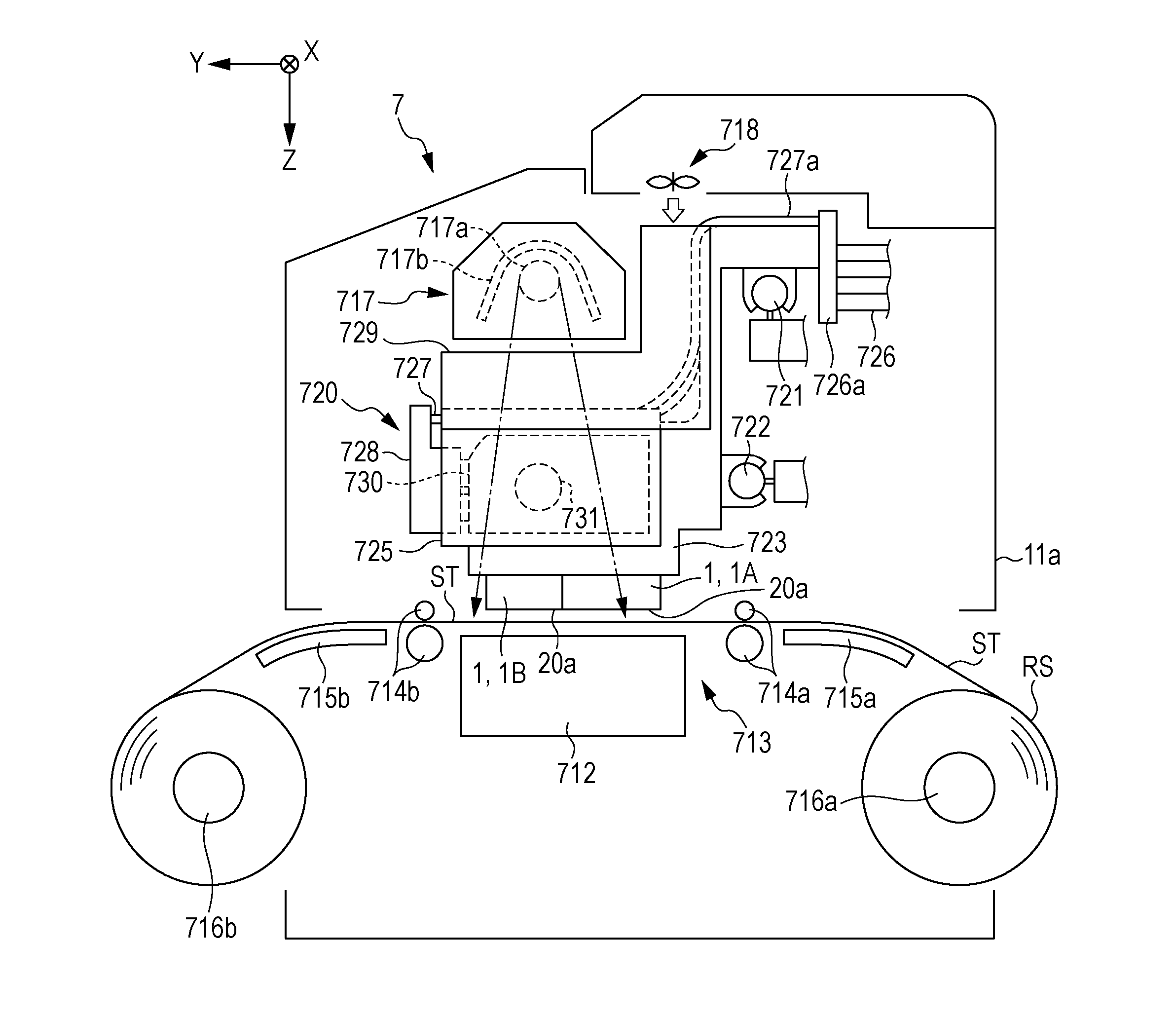
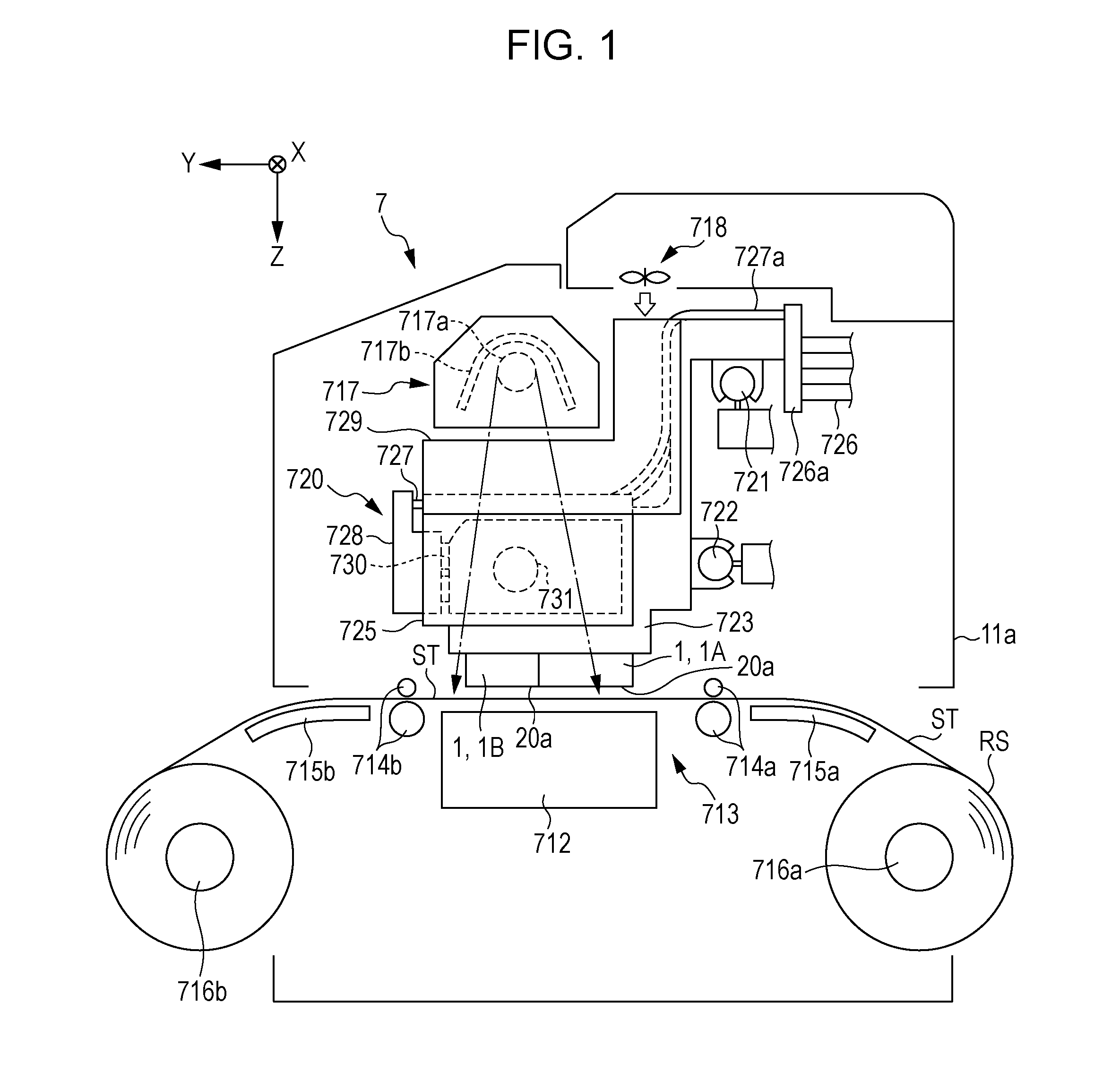
[0054]As shown in FIG. 1, the liquid ejecting apparatus 7 is provided with a transport unit 713 with which the sheet-like medium ST supported on the support stand 712 is transported in the transport direction Y along the surface of the support stand 712, a printing unit 720 that performed printing while ejecting ink as an example of the first liquid to the transported medium ST, and a heating unit 717 and a blower 718 for causing the ink landed on the medium ST to dry.

[0055]The support stand 712, the transport unit 713, the heating unit 717, the blower 718, and the printing unit 720 are assembled in a printer main body 11a configured by a housing, a frame and the like. In the printer main body 11a, the support stand 712 extends in the width direction (in FIG. 1, direction orthogonal to the paper surface) of the medium ST.

[0056]The transport unit 713 is provided with a transport roller pair 714 and a transport roller pair 714b arranged on the upstream side and the downstream side of ...

second example

[0224]Next, the second embodiment of the liquid ejecting apparatus will be described with reference to the drawings.

[0225]Since configurations to which the same reference numerals at the first embodiment are applied in the second embodiments include the same configurations as the first embodiment, description thereof will not be provided, and description below will be provided focusing on the points of difference from the first embodiment.

[0226]As shown in FIG. 16, the fluid ejecting device 775D provided in the liquid ejecting apparatus of the embodiment is configured so the direction in which the fluid ejecting nozzle 778 ejects the fluid is changeable. The position of the fluid ejecting nozzle 778 when ejecting the fluid in the first ejection direction S1 substantially orthogonal to the opening surface (liquid ejecting surface 20a) in which the nozzle 21 opens is referred to as the first position P1. The position of the fluid ejecting nozzle 778 when ejecting the fluid in the seco...


PUM


Abstract

A liquid ejecting apparatus includes a liquid ejecting unit having nozzles able to eject a first liquid to a medium; and a fluid ejecting device having ejection ports able to eject a fluid including a second liquid to the liquid ejecting unit, in which the fluid ejecting device performs, as a maintenance operation of the liquid ejecting unit, a first fluid ejection of ejecting a fluid including small droplets of the second liquid that are smaller than a nozzle opening to an opening region in which the nozzles of the liquid ejecting unit open, and a second fluid ejection of ejecting a fluid including droplets of the second liquid in which the smallest droplets are larger than the small droplets to the liquid ejecting unit.

Description

BACKGROUND[0001]1. Technical Field[0002]The present invention relates to a liquid ejecting apparatus, such as a printer.[0003]2. Related Art[0004]Among ink jet-type printers that are examples of a liquid ejecting apparatus, there are printers that discharge a cleaning agent as a mist to nozzles that eject ink, dissolve solid components of the ink fixed to the periphery of the nozzles or the vicinity of the openings and blow and remove the dissolved materials by the discharge of a gas (for example, JP-A-2002-178529).[0005]Incidentally, in a case where clogging occurs in a nozzle, it is possible to resolve the nozzle clogging by vigorously introducing droplets of a cleaning agent to the inside of the nozzle. However, the meniscus (curved liquid surface) formed inside the nozzle may collapse, and the ejection capacity of the nozzle may be lowered when droplets of the cleaning solution enter into a nozzle which is not clogged. In this way, because the results of the maintenance vary acc...

Claims


Application Information

Patent Timeline
IPC IPC(8): B41J2/165
CPCB41J2/16535B41J2/16552B41J2002/1657B41J2002/16558B41J2002/16555B41J2/16538B41J19/207
Inventor SHINBARA, TOSHIHIROHARA, KAZUHIKOKAWAKAMI, TAKAYUKIFUJIOKA, KAZUYUKIKIMURA, HITOTOSHI
Owner SEIKO EPSON CORP
Why Eureka
Try Eureka