
Insulating electrification plate ferrite applicator for a dipole lightning rod

a technology of dipole lightning rod and electrification plate, which is applied in the installation of lighting conductors, overvoltage arrestors using spark gaps, electric cable installations, etc., can solve the problem of limited expansion of the preliminary discharge current of the conventional dipole lightning protection devi

Inactive Publication Date: 2016-08-11
THE KOREA DEV BANK
View PDF0 Cites 1 Cited by
  • Summary
  • Abstract
  • Description
  • Claims
  • Application Information

AI Technical Summary

Benefits of technology

The present invention provides an insulating electrification plate ferrite applicator for a dipole lightning rod. The main technical effects of this invention include a Ferrite coating layer that increases corona pre-discharge current and lowers corona discharge starting voltage with respect to a specific element forming the dipole lightning rod. The invention also includes a spray nozzle unit that can perform a straight-line reciprocating motion horizontally and vertically, and a location tracking unit that guides the spray nozzle unit to accurately spray the ferrite coating material onto the electrification plates. Additionally, the invention includes a driving motor to move the spray nozzle unit up and down, and a fire hose for fire suppression. The applicator has a compact structure and is easy to operate, making it an efficient and effective tool for preventing lightning strike damage.

Problems solved by technology

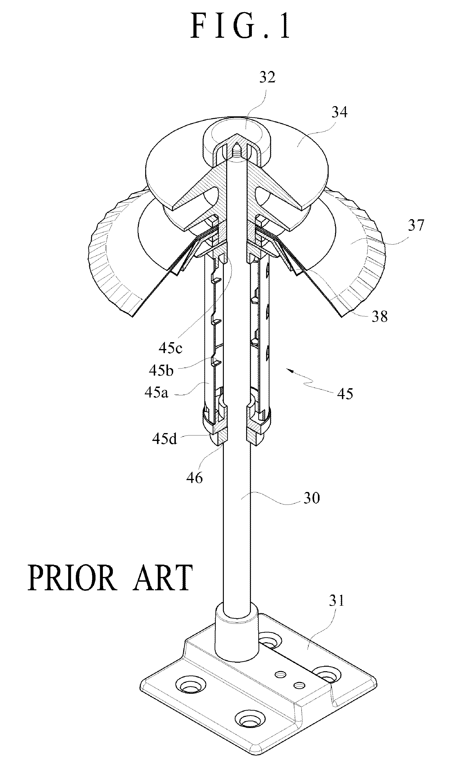
However, the conventional dipole lightning protection device configured as described above is problematic in that a preliminary discharge corona discharge start voltage is irregularly generated between the electrification plates 37 and 38 (also called “discharge-assistant members”) electrically charges when a thundercloud approaches and the rod 30 connected to charges accumulated on the electrification tube 45a and the earth.
In particular, it was found that the conventional dipole lightning protection device is limited in increasing a preliminary discharge current after the preliminary discharge start.Accordingly, the inventor has developed a plurality of technologies related to the dipole lightning protection device and had some patent rights regarding the dipole lightning protection device.

Method used


Image

  • Insulating electrification plate ferrite applicator for a dipole lightning rod
  • Insulating electrification plate ferrite applicator for a dipole lightning rod
  • Insulating electrification plate ferrite applicator for a dipole lightning rod

Examples


Embodiment Construction

[0033]Hereinafter, embodiments of the present invention are described in detail with reference to FIGS. 2 to 7.

[0034]Prior to a description, in the present invention, a term “coating” should be construed as including all of terms “cladding”, “stacking”, and “adhesion” which are collectively called “coating”, for convenience of description. A layer formed by “coating”, “cladding”, “stacking”, or “adhesion” is called a “coating layer.”

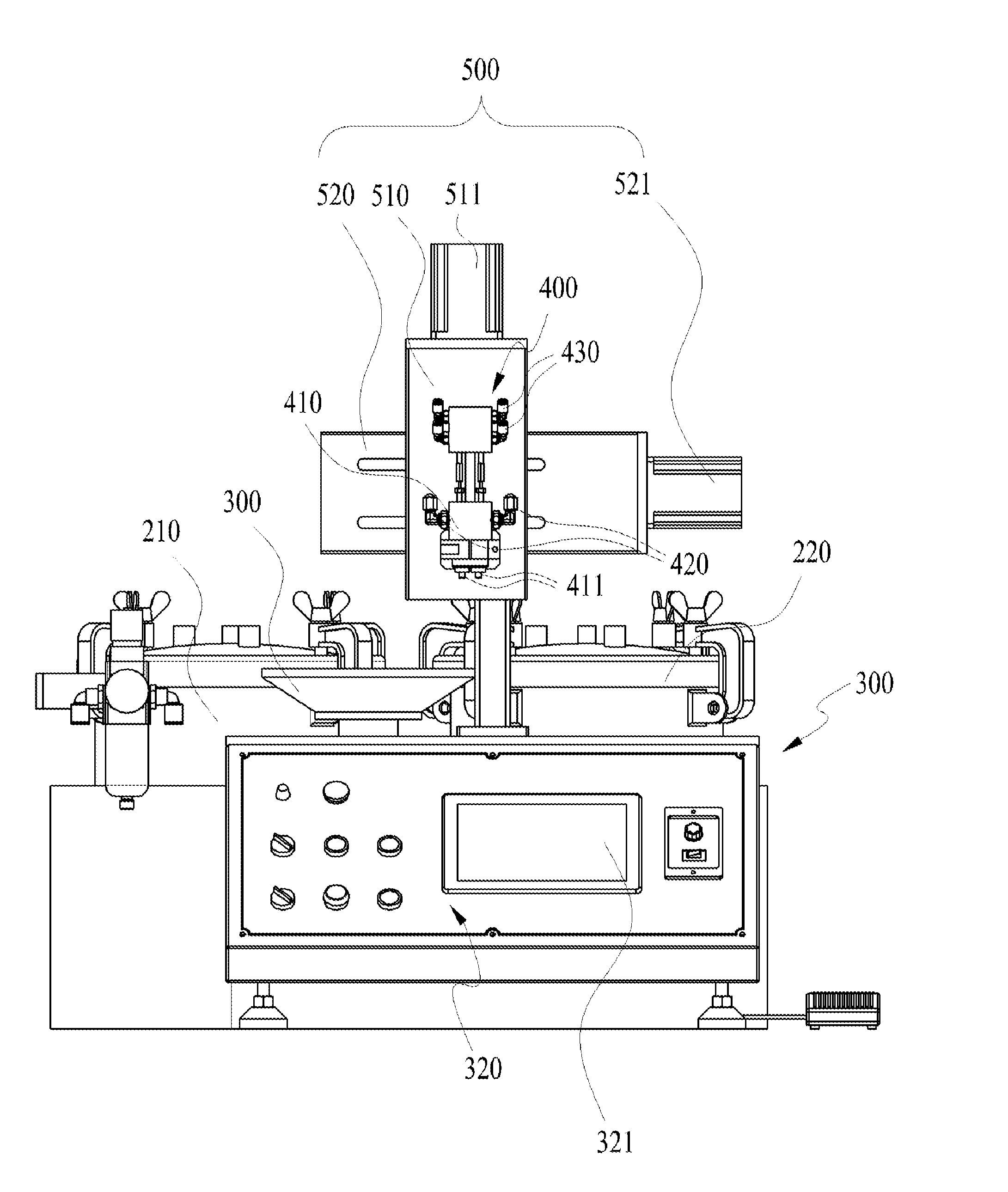
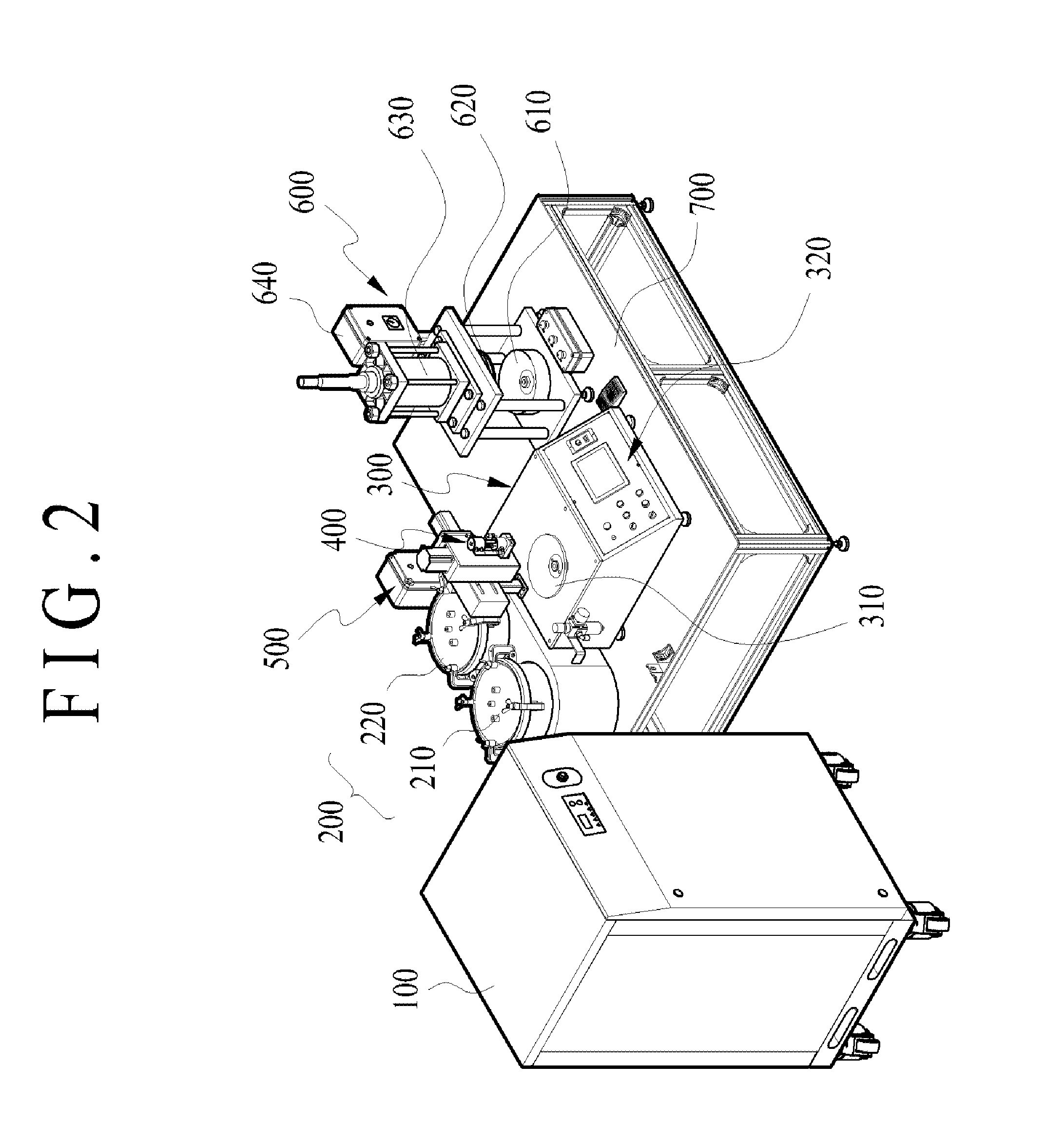
[0035]As illustrated in FIGS. 2 to 7, the insulating electrification plate ferrite applicator for a dipole lightning rod according to an embodiment of the present invention is used to previously coat a ferrite coating material on a metal electrification plate 11 before two metal electrification plates 11 and 12 of elements that form the dipole lightning rod are coalesced. The ferrite applicator may be configured to include a compression air generation unit 100 configured to generate and charge compressed air, a storage tank 200 connected to the compressi...


PUM


Abstract

Disclosed herein is an insulating electrification plate ferrite applicator for a dipole lightning rod. The ferrite applicator may include a compression air generation unit configured to generate and charge compressed air, a storage tank connected to the compression air generation unit and configured to stored a ferrite coating material, an applicator body equipped with a turntable configured to rotatably support an electrification plate and an operation control unit, a spray nozzle unit installed on top of the applicator body and configured to spray and supply the ferrite coating material, and a location tracking unit configured to guide the spray nozzle unit so that the spray nozzle unit performs a straight-line reciprocating motion horizontally and vertically. Accordingly, there are advantages in that a ferrite coating task for lowering a corona pre-discharge current and a corona preliminary discharge voltage can be automated and uniformly performed and the reliability and productivity of a task can be significantly improved.

Description

CROSS REFERENCE TO RELATED APPLICATION[0001]The present application claims the benefit of Korean Patent Application No. 10-2015-0018674 filed in the Korean Intellectual Property Office on Feb. 6, 2015, the entire contents of which are incorporated herein by reference.BACKGROUND OF THE INVENTION[0002]1. Technical Field[0003]The present invention relates to an insulating electrification plate ferrite applicator for a dipole lightning rod and, more particularly, to an insulating electrification plate ferrite applicator for a dipole lightning rod, wherein a ferrite coating layer for increasing a corona pre-discharge current and lowering a corona discharge starting voltage with respect to a specific element forming the dipole lightning rod is formed.[0004]2. Description of the Related Art[0005]In general, a lightning protection device is installed at the top of a building in order to safely discharge charges, accumulated on a thundercloud, to the earth by forming a discharge path between...

Claims


Application Information

Patent Timeline
Patent Type & Authority Applications(United States)
IPC IPC(8): B05B7/00B05B13/02B05B12/02H02G13/00
CPCB05B7/0075B05B12/02B05B13/0228H02G13/80B05B13/0405B05B12/00B05B13/041H01T4/00
Inventor CHUNG, YOUNG-KI
Owner THE KOREA DEV BANK
Learn More