
Scroll-type compressor

a compressor and roller technology, applied in the direction of machines/engines, rotary/oscillating piston pump components, liquid fuel engines, etc., can solve the problem of limiting the energy loss generated at the time of combining fluids which are different in pressure from each other, and the increase in energy loss can be sure. problem, to achieve the effect of limiting the increase in energy loss and simple configuration

Active Publication Date: 2016-08-04
DENSO CORP +1
View PDF5 Cites 4 Cited by
  • Summary
  • Abstract
  • Description
  • Claims
  • Application Information

AI Technical Summary

Benefits of technology

The present patent aims to reduce energy loss in a scroll-type compressor that pressurizes fluid in multiple stages. This is accomplished by limiting the increase in energy loss with a simple configuration, without adding a special communication passage through which multiple compression spaces communicate with each other. Additionally, the number of curling of both the low-stage and high-stage movable tooth portions is reduced, thereby reducing increase in energy loss in both portions. Overall, this results in a more efficient and compact scroll-type compressor.

Problems solved by technology

Hence, increase in energy loss generated at the time of combining the fluids which are different in pressure from each other can be limited certainly.

Method used


Image

  • Scroll-type compressor
  • Scroll-type compressor
  • Scroll-type compressor

Examples


Embodiment Construction

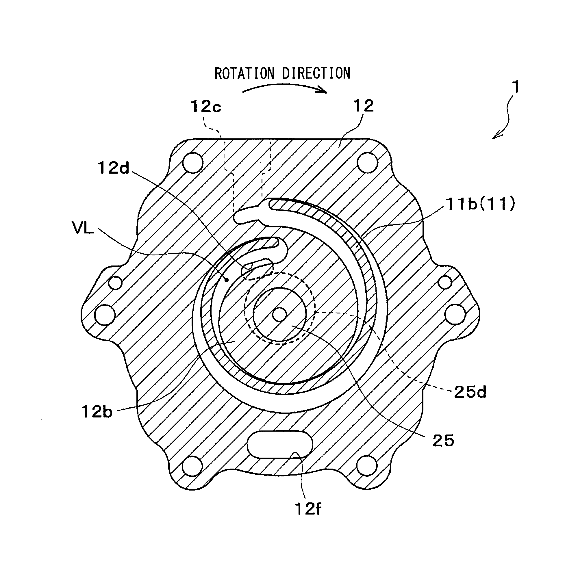
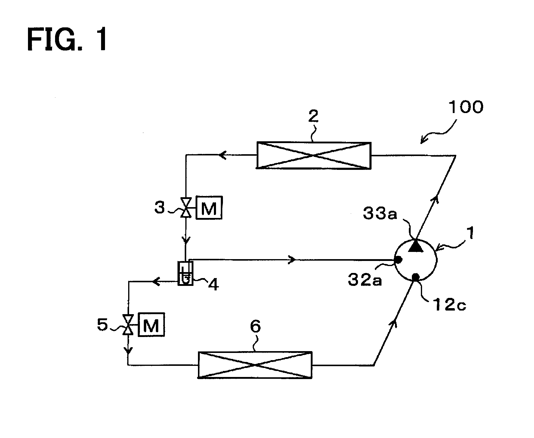
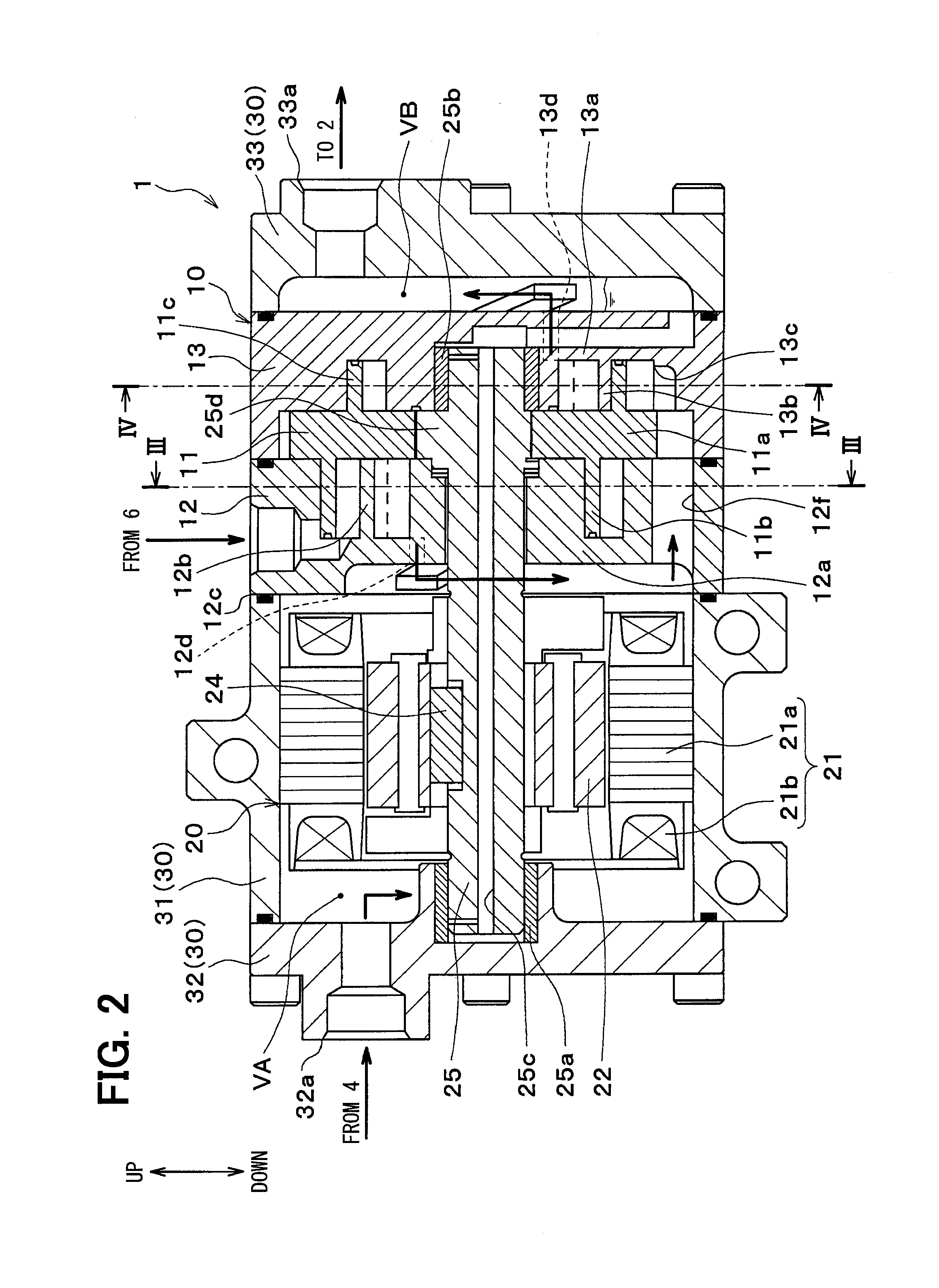
[0033]An embodiment of the present disclosure will be described below with reference to drawings. A multiple-stage pressurization scroll-type compressor 1 (hereinafter, described just as a compressor 1) according to the present embodiment is used for a refrigeration cycle 100 shown in an entire configuration diagram of FIG. 1. The refrigeration cycle 100 in an air conditioner fulfills a function to heat a blown air that is blown to an air-conditioning target space.

[0034]More specifically, the refrigeration cycle 100 of the present embodiment is a vapor-compression refrigeration cycle, which includes a compressor 1 that compresses and discharges a refrigerant, a radiator 2 that heats the blown air via heat exchange between a high-pressure refrigerant discharged from the compressor 1 and the blown air, a high-stage expansion valve 3 that depressurizes a refrigerant flowing out of the radiator 2 to be an intermediate-pressure refrigerant, a gas-liquid separator 4 that separates gas and...


PUM


Abstract

A scroll-type compressor includes: a movable scroll including a low-stage movable tooth portion having a spiral shape and protruding from a first side of a movable substrate portion in an axial direction, and a high-stage movable tooth portion having a spiral shape and protruding from a second side of the movable substrate portion in the axial direction; and a shaft arranged to extend through the movable substrate portion and causing the movable scroll to undergo revolution motion. A low-stage compression mechanism and a high-stage movable compression mechanism are provided on opposite sides of the movable substrate portion in the axial direction. The numbers of curling of the low-stage movable tooth portion and the high-stage movable tooth portion are set to be one.

Description

CROSS REFERENCE TO RELATED APPLICATION[0001]This application is based on and incorporates herein by reference Japanese Patent Application No. 2013-217072 filed on Oct. 18, 2013.TECHNICAL FIELD[0002]The present disclosure relates to a scroll-type compressor that pressurizes a fluid in multiple stages.BACKGROUND ART[0003]Conventionally, in Patent Document 1, a scroll-type compressor is disclosed as a compressor used for a so-called gas injection cycle (economizer refrigeration cycle), and includes a low-stage scroll compression mechanism (hereinafter, described as a low-stage compression mechanism), and a high-stage scroll compression mechanism (hereinafter, described as a high-stage compression mechanism). The compressor pressurizes a refrigerant (fluid) in multiple stages in these multiple compression mechanisms.[0004]Like the scroll-type compressor of Patent Document 1, in a compressor including multiple compression mechanisms, a size of the compressor is likely to be large as a wh...

Claims


Application Information

Patent Timeline
Patent Type & Authority Applications(United States)
IPC IPC(8): F04C28/20F04C29/00F04C29/12F04C18/02
CPCF04C23/001F04C23/008F04C18/0223F04C29/12F04C18/0269F04C28/20F04C29/0057F04C18/0215
Inventor OHNO, YUICHIUCHIDA, KAZUHIDEHIGASHIYAMA, MASASHI
Owner DENSO CORP
Learn More