
Micro-machined vapor cell

a vapor cell and micro-machine technology, applied in the direction of pulse automatic control, pre-selected time interval producing apparatus, instruments, etc., can solve the problems of inability to adjust the strength of the magnetic field, the final device is quite bulky, and the reference to the portable application of the vapor cell cannot be found, so as to improve the control of the assembled components, reduce the volume, and reduce the effect of electrical resistan

Active Publication Date: 2016-07-28
CSEM CENT SUISSE DELECTRONIQUE & DE MICROTECHNIQUE SA RECH & DEV
View PDF0 Cites 23 Cited by
  • Summary
  • Abstract
  • Description
  • Claims
  • Application Information

AI Technical Summary

Benefits of technology

This patent describes a vapor cell that uses magnetic means to create a small atomic clock. The main benefits of this design are that it doesn't add much extra space and has very low electrical resistance compared to traditional designs. The goal of this invention is to create more efficient and controllable miniature atomic clocks.

Problems solved by technology

For cesium and rubidium, this wavelength is of the order of several centimeters, clearly posing a problem for the development of vapor cell references for portable applications.
One option is the use of permanent magnets, but they present the disadvantage that the strength of the magnetic field cannot be adjusted, and that they make the final device quite bulky.
As a consequence, a planar coil has a relatively high electrical resistance and hence an elevated power dissipation.
Thus, a skilled person is not encouraged to investigate planar coils for providing a homogeneous magnetic field in a miniaturized vapor cell.

Method used


Image

  • Micro-machined vapor cell
  • Micro-machined vapor cell
  • Micro-machined vapor cell

Examples


example 1

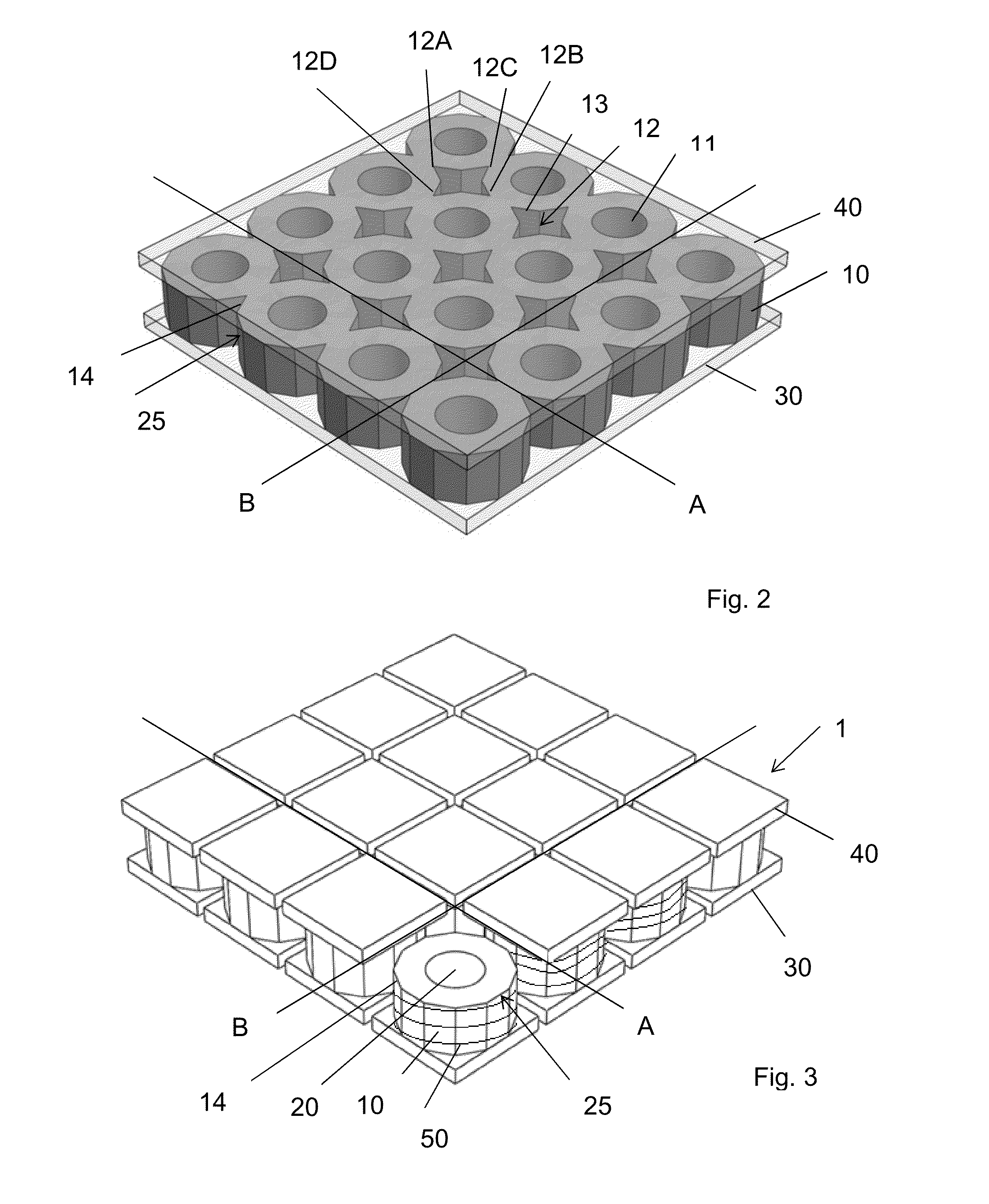
[0046]A micro-machined vapor cell comprises:[0047]a central silicon element forming a cavity containing vapor cell reactants such as alkali metal or alkali metal azide, buffer gas(es), and / or anti relaxation coating(s),[0048]a first and a second glass caps sealing the cavity, and[0049]a solenoid arranged to provide a homogeneous magnetic field to said vapor cell,

[0050]characterized in that the solenoid is coiled directly on the central silicon element, which forms the core of the solenoid.

example 2

[0051]The micro-machined vapor cell according to example 1, characterized in that the first and second glass caps define banking means to keep the solenoid coiled on the central silicon element.

example 3

[0052]The micro-machined vapor cell according to example 2, characterized in that the first and second glass caps exceed the central silicon element.


PUM


Abstract

The invention concerns a micro-machined vapor cell comprising a central silicon element forming a cavity containing vapor cell reactants such as alkali metal or alkali metal azide, buffer gas(es), and / or anti relaxation coating(s); a first and a second glass caps sealing the cavity; and a solenoid arranged to provide a homogeneous magnetic field to said vapor cell. The solenoid is coiled directly on the central silicon element of the vapor cell. This invention is an improvement for the highly miniaturized atomic clocks developments.

Description

TECHNICAL FIELD[0001]The invention relates to highly miniaturized atomic clocks. The invention particularly concerns micro-machined chip-sized vapor cells with volumes on the order of a few cubic millimeters or less. The invention also concerns a method to fabricate the aforementioned vapor cells.BACKGROUND OF THE INVENTION[0002]Miniaturized atomic clocks characterized by a small size and a drastically reduced power consumption compared to standard atomic clocks exhibit an increasing interest mainly for applications in portable devices. The unprecedented frequency stability of atomic clocks is achieved by a suitable interrogation of optically excited atoms in order to achieve the hyperfine splitting of the electron state of the reactant, which takes place in the so-called vapor cell, the heart of an atomic clock. The vapor cell comprises a sealed cavity, which contains small amounts of suitable reactants: an alkali metal, preferably rubidium or cesium, buffer gas(es), and / or anti-re...

Claims


Application Information

Patent Timeline
IPC IPC(8): H03L7/26
CPCG04F5/14H03L7/26G04F5/145
Inventor OVERSTOLZ, THOMASHAESLER, JACQUES
Owner CSEM CENT SUISSE DELECTRONIQUE & DE MICROTECHNIQUE SA RECH & DEV
Learn More