Bus bar unit, method for manufacturing bus bar unit, and brushless motor

Inactive Publication Date: 2016-07-28
MITSUBA CORP
View PDF1 Cites 21 Cited by
  • Summary
  • Abstract
  • Description
  • Claims
  • Application Information

AI Technical Summary

Benefits of technology

The bus bar unit described in this patent text has several technical effects. Firstly, by bending an elongated plate-shaped member into the shape of a bus bar, it is possible to improve yield and decrease manufacturing costs. Secondly, the width of the connection portion between bus bar pieces is narrower than the width of the bus bar piece, making it easy to bend the elongated plate-shaped member. Lastly, by arranging the phase bus bar and neutral point bus bar in a way that they are laminated along the axial direction of the bus bar unit, the size of the bus bar unit in the axial direction is decreased, and by arranging them in the radial direction, the size of the bus bar unit in the radial direction is suppressed from increasing. Overall, this bus bar unit is able to decrease the size while decreasing manufacturing costs.

Problems solved by technology

In this case, many portions of the metal plate material are not used (end material), yield deteriorates, and there is a problem in that the manufacturing cost of the bus bar unit increases.

Method used


Image

  • Bus bar unit, method for manufacturing bus bar unit, and brushless motor
  • Bus bar unit, method for manufacturing bus bar unit, and brushless motor
  • Bus bar unit, method for manufacturing bus bar unit, and brushless motor

Examples


first embodiment

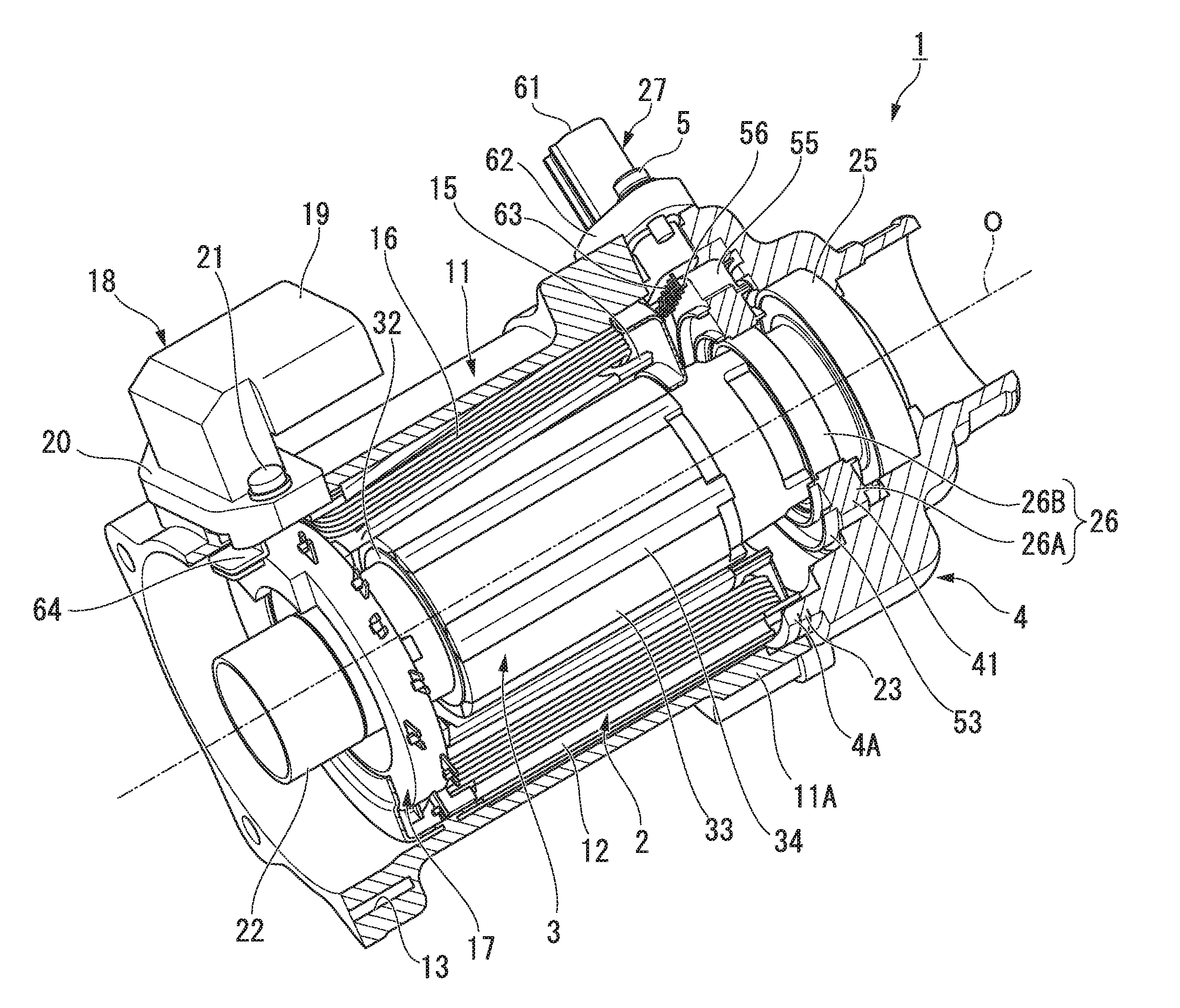
[0049]A first embodiment of the present invention will be described with reference to the drawings. After a brushless motor 1 according to the first embodiment is described, a bus bar unit will be described. In addition, in descriptions below, a direction along a center axis O of the brushless motor 1 is referred to as an axial direction, a direction orthogonal to the center axis O is referred to as a radial direction, and a direction circulating around the center axis O is referred to as a circumferential direction.

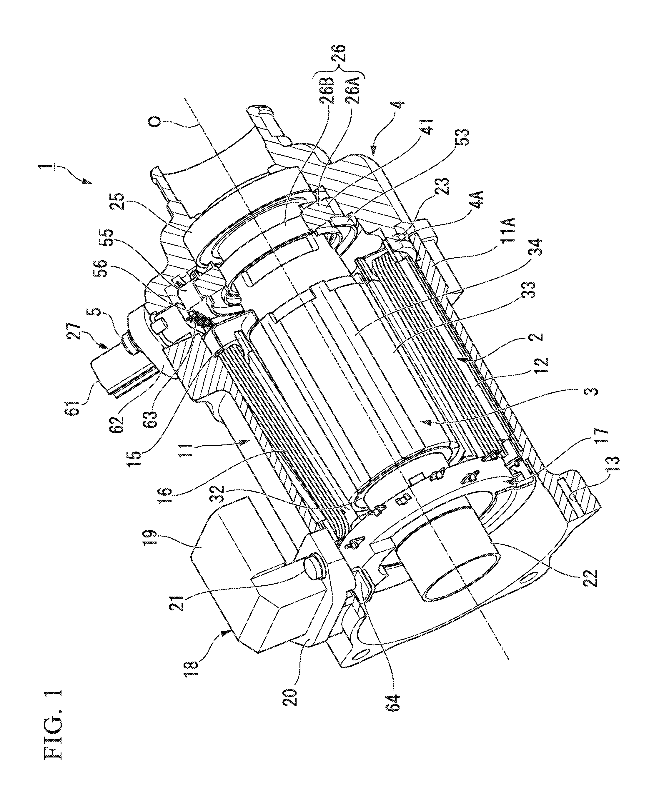
[0050]FIG. 1 is a perspective sectional view showing the brushless motor 1, and FIG. 2 is a perspective view showing a stator core 12.

[0051]As shown in FIGS. 1 and 2, for example, the brushless motor 1 is used as a drive source of an Electric Power Steering (EPS), and includes a stator 2 and a rotor 3 which is disposed inside the stator 2. The rotor 3 is rotatably supported with respect to a bracket 4 which is fixed to the stator 2.

[0052]A rack shaft (not shown) is inser...

modification example

Each Modification Example of First Embodiment

[0118]FIG. 11 is an explanatory view of a neutral point bus bar 81 according to a first modification example of the first embodiment.

[0119]FIG. 12 is an explanatory view of a neutral point bus bar 81 according to a second modification example of the first embodiment.

[0120]Modifications of the first embodiment will now be described.

[0121]In the first embodiment, the neutral point bus bar 81 includes the connection portions 83 which connect the adjacent bus bar pieces 82 to each other, and each connection portion 83 includes the non-deformation portion 84, and the deformation portions 85 which are provided on both ends in the circumferential direction of the non-deformation portion 84 (refer to FIG. 6).

[0122]The connection portion 83 is not limited to the shape of the first embodiment, and may be the connection portions 83 according to the following modification examples. In addition, descriptions below with respect to configurations simila...

second embodiment

[0126]FIG. 13 is a perspective view showing a bus bar unit 17 according to a second embodiment.

[0127]In the bus bar unit 17 according to the first embodiment, the U-phase bus bar 47U, the V-phase bus bar 47V, the W-phase bus bar 47W, and the neutral point bus bar 81 are molded in the state where the bars are laminated at predetermined intervals in the axial direction, and are held by the resin-molded body 46 (refer to FIG. 3).

[0128]As shown in FIG. 13, the bus bar unit 17 according to the second embodiment is different from the first embodiment in that the bars are held by a cylindrical bus bar holder 146. In addition, descriptions below with respect to configurations similar to those of the first embodiment are omitted.

[0129]The bus bar unit 17 according to the second embodiment includes the cylindrical bus bar holder 146. For example, the bus bar holder 146 is formed of a resin material in advance, and approximately four annular groove portions 146a to 146d along the circumferenti...


PUM


Abstract

A bus bar unit is configured to supply power to coils (16) of a plurality of phases, and includes phase bus bars (47U ), (47V), and (47W) which are provided for each phase and are connected to winding start ends of the coils, and a neutral point bus bar (81) which is connected to winding finish ends of the coils, the neutral point bus bar (81) being formed by bending an elongated plate-shaped member such that a width direction of the elongated plate-shaped member and a radial direction of the bus bar unit coincide with each other, and including a plurality of bus bar pieces (82) and a connection portion (83) which connects the bus bar pieces (82) and (82) adjacent to each other, and a width of a deformation portion (85) of the connection portion (83) being narrower than a width of the bus bar piece (82).

Description

TECHNICAL FIELD[0001]The present invention relates to a bus bar unit, a method for manufacturing a bus bar unit, and a brushless motor.[0002]Priority is claimed on Japanese Patent Application No. 2013-200139, filed Sep. 26, 2013, the content of which is incorporated herein by reference.BACKGROUND ART[0003]In general, an inner rotor type brushless motor includes a stator which is internally fitted so as to be fixed to the motor case, and a rotor which is disposed at the center in a radial direction of the motor case and is rotatably supported with respect to the stator. Plural permanent magnets are disposed on the outer circumferential surface of the rotor. The stator includes an approximately cylindrical stator core, and plural teeth which protrude to the inside in the radial direction from the stator core.[0004]An insulator which is formed of a resin material having an insulation property is mounted on each tooth, and a coil is wound around the teeth with the insulator interposed. ...

Claims


Application Information

Patent Timeline
IPC IPC(8): H02K3/28H02K15/00H02K3/38
CPCH02K3/28H02K15/0062H02K3/38H02K3/522H02K5/225H02K2203/09H02K11/225H02K15/0068
Inventor YAMADA, YUICHISHIMBO, YUTAKANARA, KOJINISHIMURA, YOSHIHIROTAKEARA, TOSHIHIROOKAMOTO, ATSUSHIOZAWA, YUTAKATSUTA, ATSUSHINISHIGORI, SATOSHI
Owner MITSUBA CORP
Why Eureka
Try Eureka