
Vacuum tube

a vacuum tube and tube body technology, applied in the field of vacuum tubes, can solve the problems of increasing price and difficulty in availability, reducing the quantity of vacuum tubes to be used as analog amplifiers, and not being easily used for analog amplification by vacuum fluorescent displays. , to achieve the effect of convenient us

Active Publication Date: 2016-07-21
NORITAKE ITRON CORP +1
View PDF1 Cites 1 Cited by
  • Summary
  • Abstract
  • Description
  • Claims
  • Application Information

AI Technical Summary

Benefits of technology

The present invention is a vacuum tube with a structure similar to a cheap and readily available vacuum fluorescent display. It can be easily operated as an analog amplifier by changing the flow of electrons from a filament to an anode using the electric potential of a grid. This makes the vacuum tube easy to use for amplifying signals in an analog way.

Problems solved by technology

Therefore, the quantity of production of vacuum tubes to be used as analog amplifiers decreases, and there are problems of increase in price and difficulty in availability.
On the other hand, a vacuum fluorescent display, which is a kind of vacuum tube and is available inexpensively, is digitally controlled as is known from the driving system shown in Reference Literature 1 and is not designed for use as an analog amplifier.
Therefore, the vacuum fluorescent display is not easily used for analog amplification.

Method used


Image

  • Vacuum tube
  • Vacuum tube
  • Vacuum tube

Examples


first embodiment

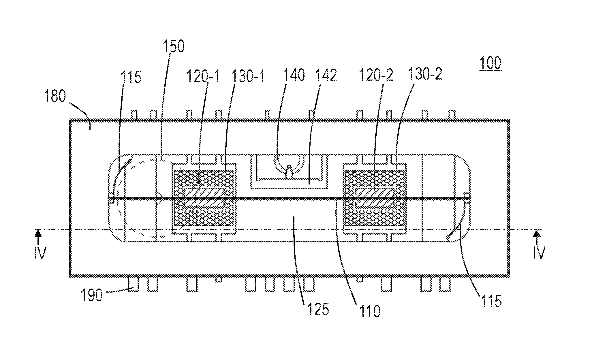
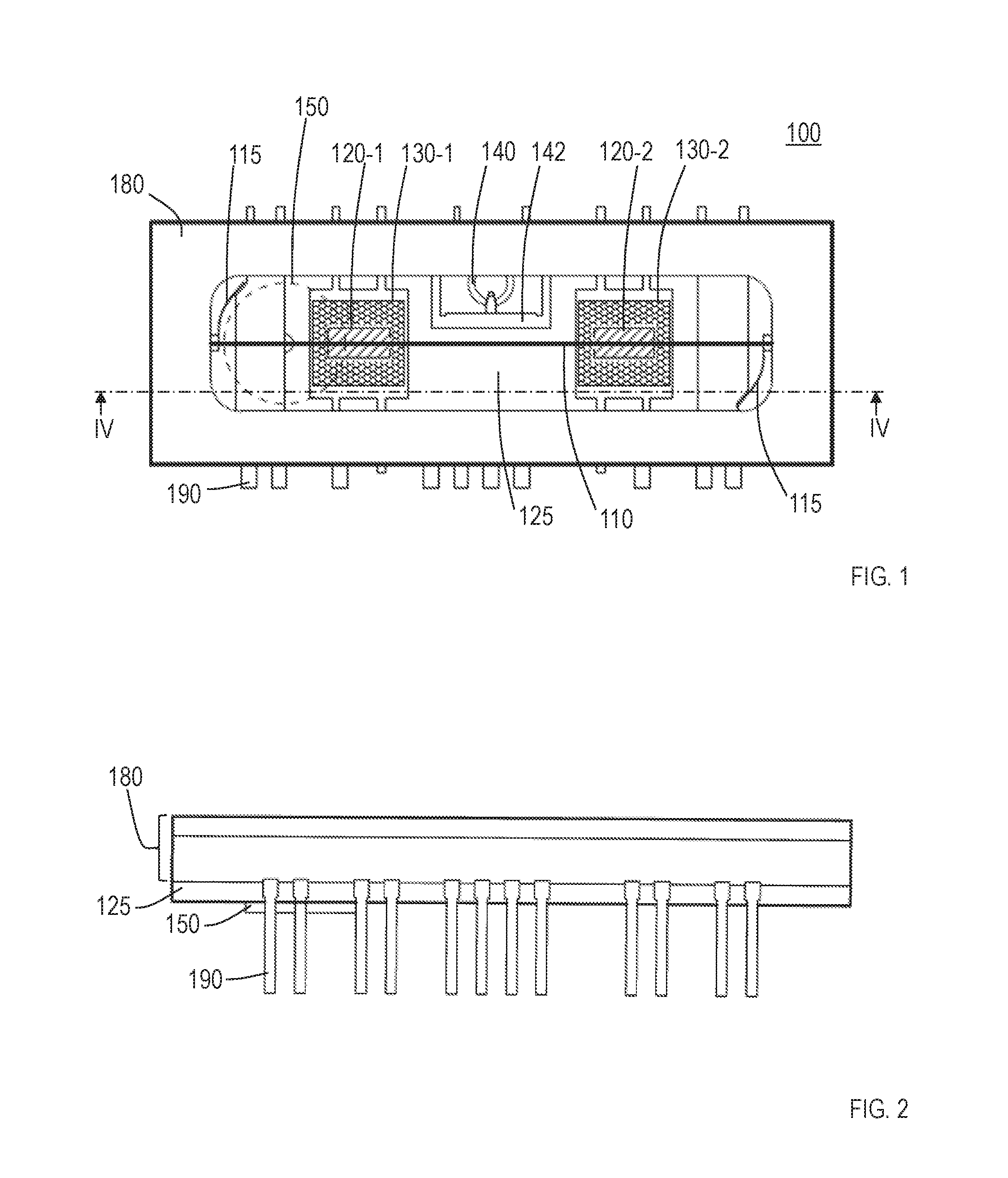
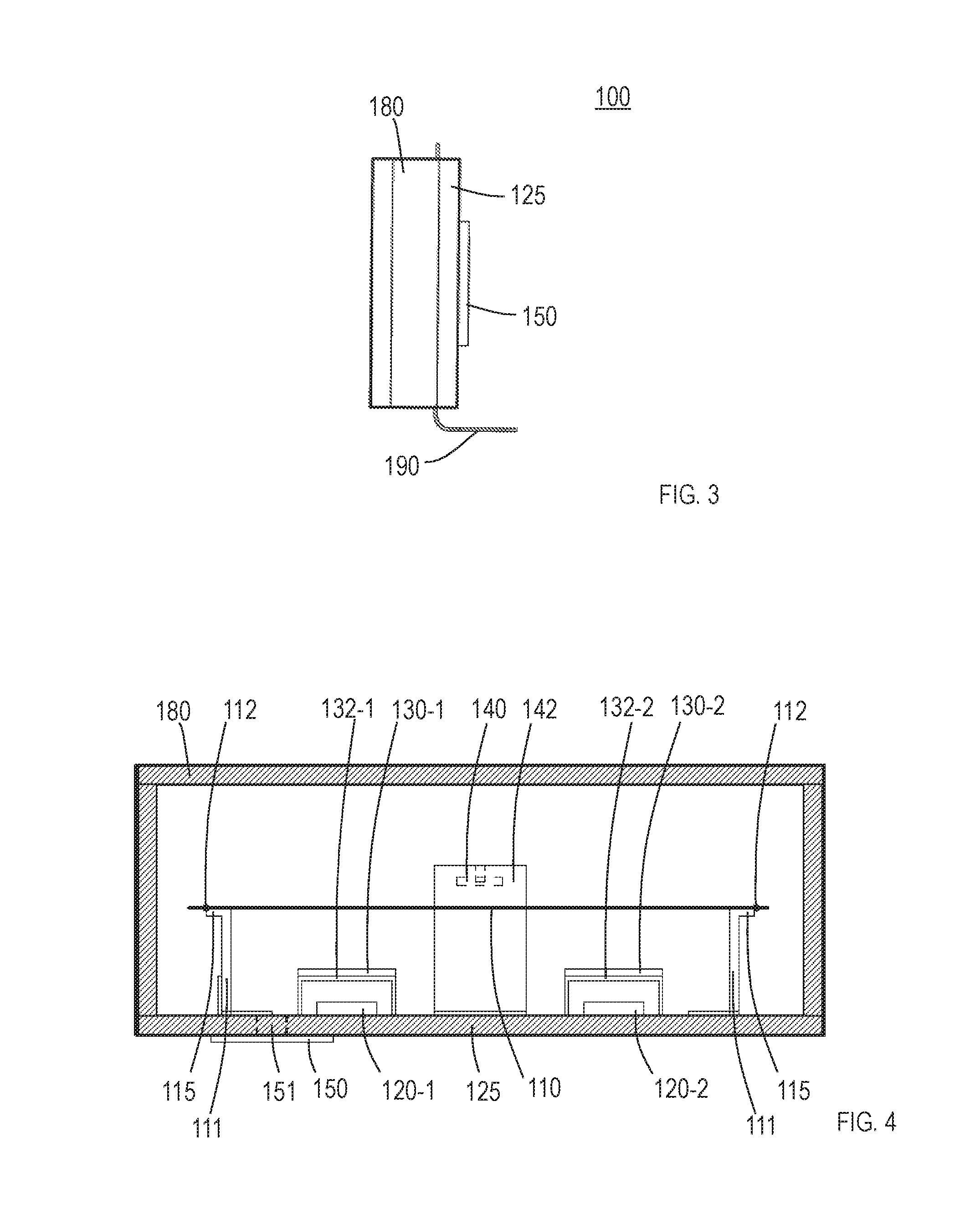
[0023]A plan view, front view and side view of a vacuum tube of a first embodiment are shown in FIG. 1, FIG. 2 and FIG. 3, respectively, and a cross-sectional view at a IV-IV line in FIG. 1 is shown in FIG. 4. FIG. 4 is vertically enlarged so that a structure can be easily understood. Though the ratio of vertical direction to horizontal direction is different between FIG. 2 and FIG. 4, it is actually the same. A vacuum tube 100 comprises: a filament 110 which is tensioned linearly and emits thermoelectrons at a predetermined temperature or higher, anodes 120-1, 120-2 arranged parallel to the filament 110, a grid 130-1 arranged between the filament 110 and the anode 120-1 such that the grid 130-1 faces the anode, and a grid 130-2 arranged between the filament 110 and the anode 120-2 such that the grid 130-2 faces the anode. It is a (first) feature that a distance between the filament 110 and the grids 130-1, 130-2 is between 0.2 mm and 0.6 mm, including 0.2 mm and 0.6 mm. Furthermore...


PUM


Abstract

An object of the present invention is to provide a vacuum tube with a structure close to that of an inexpensive and easily available vacuum fluorescent display which easily operates as an analog amplifier. A vacuum tube subject to the present invention comprises: a filament which is tensioned linearly and emits thermoelectrons, an anode arranged parallel to the filament, and a grid arranged between the filament and the anode such that the grid faces the anode. The present invention is characterized in that a distance between the filament and the grid is between 0.2 mm and 0.6 mm, including 0.2 mm and 0.6 mm.

Description

TECHNICAL FIELD[0001]The present invention relates to a vacuum tube which operates as an analog amplifier.BACKGROUND ART[0002]A vacuum fluorescent display is known as a technique related to a vacuum tube, and, for example, structures shown in Japanese Utility Model Publication No. 49-5240 (hereinafter referred to as “Patent Literature 1”) and Japanese Patent Application Laid Open No. 2007-42480 (hereinafter referred to as “Patent Literature 2”) are known. In Patent Literature 1, a linearly tensioned filament which emits thermoelectrons at a predetermined temperature or higher is referred to as “a heater H”. An anode arranged parallel to the filament (“a positive pole 4” in Patent Literature 1), and a grid arranged between the filament and the anode such that the grid faces the anode are provided (see FIGS. 1 and 2 of Patent Literature 1). A basic structure in Patent Literature 2 is the same as that of Patent Literature 1. As a control method for the vacuum fluorescent display shown ...

Claims


Application Information

Patent Timeline
Patent Type & Authority Applications(United States)
IPC IPC(8): H01J21/06H01J19/70
CPCH01J19/70H01J21/06H01J19/04H01J21/10H01J19/32H01J19/38
Inventor TATSUDA, KAZUNORIMAEDA, TADAMIYAMANAKA, MISA
Owner NORITAKE ITRON CORP
Learn More