Low-Voltage Switching Device With A Variable Design

a low-voltage switching and variable-design technology, applied in the direction of electromagnetic relays, electrical apparatus, electromagnetic relay details, etc., can solve the problems of increased production costs of these devices, complex and complete tooling for their production, and easy failure and dimensional deviation

Active Publication Date: 2016-07-21
SIEMENS AG
View PDF15 Cites 1 Cited by
  • Summary
  • Abstract
  • Description
  • Claims
  • Application Information

AI Technical Summary

Benefits of technology

[0004]It is accordingly an object of the present invention to provide a low-voltage switching device which can be adapted to different device designs in the simplest possible manner.

Problems solved by technology

Basic elements for these devices, such as arcing chambers or contact carriers, notwithstanding the relatively small production runs involved in some cases, nevertheless require complex and complete tooling for their production.
This results in increased production costs for these devices which, as a result of the highly complex tools involved in the routine production process, are also susceptible to failures and dimensional deviations.

Method used


Image

  • Low-Voltage Switching Device With A Variable Design
  • Low-Voltage Switching Device With A Variable Design
  • Low-Voltage Switching Device With A Variable Design

Examples


Embodiment Construction

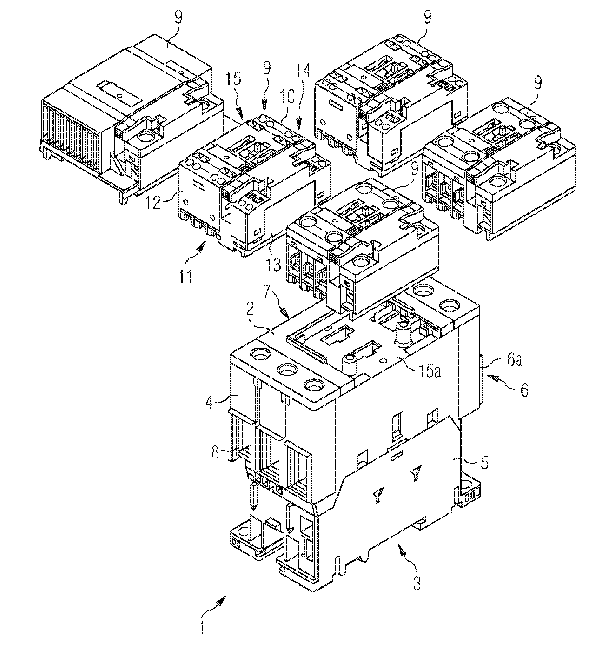
[0024]FIG. 1 depicts a low-voltage switching device, in particular a contactor, constructed in accordance with the invention. The low-voltage switching device is configured in two parts, including a base module 1 that is preferably of cuboid design and includes an upper side 2, an underside 3 and four lateral elements 4, 5, 6, 7. A connection region 6a and 8 for electrical conductors is preferably arranged on the lateral elements 4 and 6. A separate auxiliary module 9, which is attachable to and detachable from the base module 1, is preferably arranged on the upper side 2 of based module 1. Auxiliary module 9—several distinct forms of which are depicted in FIG. 2—may be configured as a standard auxiliary module, as a communication auxiliary module, or as a capacitor switching contactor auxiliary module. The auxiliary module 9 is preferably also of cuboid design, with an upper side 10, an underside 11 and four lateral elements 12, 13, 14, 15. The auxiliary module 9 is mountable on th...


PUM


Abstract

A low-voltage switching device includes a base module, with a connection region for electrical conductors. Auxiliary contacts and a coil connection are arranged in a separate auxiliary module that is attachable to and detachable from the base module to maximize flexibility in configuration, manufacture, functionality and utility of the switching device while reducing production costs.

Description

FIELD OF THE INVENTION[0001]The present invention relates to a low-voltage switching devices with a base module that includes a connection region for electric conductors.BACKGROUND OF THE INVENTION[0002]For low-voltage switching devices, specifically contactors, a variety of switching device designs are available for different industrial applications. For example, for the switching of motors, three-pole or four-pole switching devices are required, while the switching of capacitor banks requires special capacitor switching contactors for reactive power compensation and special contactor designs which permit communication with a programmable logic controller (PLC). All of these switching device designs are also associated with requirements for different connection options, including screw connectors, spring-loaded terminals or ring cable shoe connectors.[0003]To date, these switching device designs have been realized using specific devices produced for this purpose. Basic elements for...

Claims


Application Information

Patent Timeline
Patent Type & Authority Applications(United States)
IPC IPC(8): H01H9/02H01H9/34H01H9/00
CPCH01H9/02H01H9/34H01H9/0066H01H50/021H01H50/14H01H50/443H01H2011/0037H01H50/545
Inventor ZIMMERMANN, NORBERT
Owner SIEMENS AG
Why Eureka
Try Eureka