Low-voltage switching device with a variable design

a low-voltage switching and variable-design technology, applied in the direction of electromagnetic relays, electrical apparatus, electromagnetic relay details, etc., can solve the problems of increased production costs of these devices, complex and complete tooling for their production, and easy failure and dimensional deviation

Active Publication Date: 2019-02-26
SIEMENS AG
View PDF28 Cites 0 Cited by
  • Summary
  • Abstract
  • Description
  • Claims
  • Application Information

AI Technical Summary

Benefits of technology

[0005]It is accordingly an object of the present invention to provide a low-voltage switching device which can be adapted to different device designs in the simplest possible manner.
[0007]By utilizing this variable, modular design of the inventive low-voltage switching devices, it is possible to produce, by exchanging individual device components, any of a wide variety of switching device designs that may be required for a particular application. Accordingly, for example, by exchanging one device component, in the present case by exchanging the auxiliary module, it is possible to incorporate provision for a variety of connection systems. The auxiliary module according to the invention can be manufactured using easily-produced tools. In the auxiliary module, individual device components continue to be used universally, without changes. By the corresponding configuration of the auxiliary module, further device designs can be produced including, for example, capacitor contactors or contactors for communication applications. As a result of its characteristic unit design, the auxiliary module according to the invention is also suitable for application in different sizes.
[0008]The core feature of the invention is a variable device design, resulting from use of a base module and a separate or separable auxiliary module. By the corresponding configuration of the auxiliary module, by means of exchanging or the assembly of the device in a given manufacturing process, switching devices of different designs can easily be produced. This is advantageously associated with a reduction in the variety of components, as a result of the modular application of individual components or individual sub-assemblies. This leads to a cost reduction in the design of devices, associated with automation, specifically in the manufacture of small switching device production runs. There is a further advantage, in that a simpler, and consequently more cost-effective production of tools is possible. A further advantage is associated with the separation of the main control level from the auxiliary control level, whereby the main control level is arranged in the base module and the auxiliary control level is arranged in the auxiliary module. Accordingly, basic devices can also be converted subsequent in time. It is consequently also possible to employ abrasion-optimized material combinations for the main and auxiliary control circuits. As the auxiliary modules according to the invention, on the grounds of their characteristic unit design, can encompass different sizes, an advantageous reduction in the variety of components or sub-assemblies is possible. Moreover, this provides an advantage in that assembly of the requisite switching devices can be completed rapidly and in situ.
[0018]The present invention is characterized by variable device design, resulting from the use of a base module and an auxiliary module. By the corresponding configuration of the auxiliary module, through exchange or assembly of the device in a given manufacturing process, switching devices of different designs can easily be produced. This is advantageously associated with a reduction in the variety of components, as a result of the modular application of individual components or individual sub-assemblies. This leads to a cost reduction in the design of devices, associated with automation, specifically in the manufacture of small switching device production runs. As a further advantage, the simpler and consequently more cost-effective production of tools is possible.

Problems solved by technology

Basic elements for these devices, such as arcing chambers or contact carriers, notwithstanding the relatively small production runs involved in some cases, nevertheless require complex and complete tooling for their production.
This results in increased production costs for these devices which, as a result of the highly complex tools involved in the routine production process, are also susceptible to failures and dimensional deviations.

Method used


Image

  • Low-voltage switching device with a variable design
  • Low-voltage switching device with a variable design
  • Low-voltage switching device with a variable design

Examples


Embodiment Construction

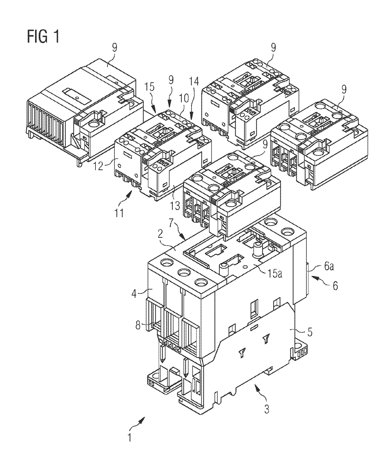
[0025]FIG. 1 depicts a low-voltage switching device, in particular a contactor, constructed in accordance with the invention. The low-voltage switching device is configured in two parts, including a base module 1 that is preferably of cuboid design and includes an upper side 2, an underside 3 and four lateral elements 4, 5, 6, 7. A connection region 6a and 8 for electrical conductors is preferably arranged on the lateral elements 4 and 6. A separate auxiliary module 9, which is attachable to and detachable from the base module 1, is preferably arranged on the upper side 2 of based module 1. Auxiliary module 9—several distinct forms of which are depicted in FIG. 2—may be configured as a standard auxiliary module, as a communication auxiliary module, or as a capacitor switching contactor auxiliary module. The auxiliary module 9 is preferably also of cuboid design, with an upper side 10, an underside 11 and four lateral elements 12, 13, 14, 15. The auxiliary module 9 is mountable on th...


PUM


Abstract

A low-voltage switching device includes a base module, with a connection region for electrical conductors. Auxiliary contacts and a coil connection are arranged in a separate auxiliary module that is attachable to and detachable from the base module to maximize flexibility in configuration, manufacture, functionality and utility of the switching device while reducing production costs.

Description

CROSS-REFERENCE TO RELATED APPLICATION[0001]This is a U.S. national stage of application No. PCT / EP2013 / 068980 filed 13 Sep. 2013.FIELD OF THE INVENTION[0002]The present invention relates to a low-voltage switching devices with a base module that includes a connection region for electric conductors.BACKGROUND OF THE INVENTION[0003]For low-voltage switching devices, specifically contactors, a variety of switching device designs are available for different industrial applications. For example, for the switching of motors, three-pole or four-pole switching devices are required, while the switching of capacitor banks requires special capacitor switching contactors for reactive power compensation and special contactor designs which permit communication with a programmable logic controller (PLC). All of these switching device designs are also associated with requirements for different connection options, including screw connectors, spring-loaded terminals or ring cable shoe connectors.[00...

Claims


Application Information

Patent Timeline
Patent Type & Authority Patents(United States)
IPC IPC(8): H01H9/02H01H9/00H01H9/34H01H50/44H01H50/14H01H50/02H01H11/00H01H50/54
CPCH01H9/02H01H9/0066H01H9/34H01H50/443H01H50/14H01H2011/0037H01H50/021H01H50/545
Inventor ZIMMERMANN, NORBERT
Owner SIEMENS AG
Why Eureka
Try Eureka