
Method for Optimizing Occlusion in Augmented Reality Based On Depth Camera

a technology of depth camera and optimization method, applied in the field of optimizing occlusion, can solve the problems of inconsistency or information loss of depth data, error generation of laser speckles, and problem likely to occur around the object edges, so as to improve the visualization result and optimize the occlusion processing

Active Publication Date: 2016-07-21
NATIONAL TSING HUA UNIVERSITY
View PDF0 Cites 14 Cited by
  • Summary
  • Abstract
  • Description
  • Claims
  • Application Information

AI Technical Summary

Benefits of technology

This patent aims to improve the visualization of augmented reality applications using depth cameras. It focuses on solving issues related to missing depth data pixels, uneven occluded edges / silhouettes, and jittering of the occluded edges / silhouettes. The method provides solutions to these issues and provides adjustable parameters for different conditions. Overall, this invention optimizes the occlusion between virtual models and the real scene in augmented reality applications.

Problems solved by technology

When the infrared light is projected onto an object in the scene, errors may be generated in the laser speckles due to various reasons such as occlusion or poor reflective properties on the object surface.
This problem is likely to occur around the object edges.
In addition, random noises of the laser speckles sometimes cause inconsistency or information loss of the depth data.
As a result, the depth image taken by depth cameras becomes unstable and jittering.
The Z-buffer method tends to produce incorrect occlusion result with depth data of poor quality.
For instance, some depth data pixels are lost, failing to occlude the virtual object properly.
The object edges or silhouettes occluded often become rugged.
Moreover, the data inconsistency between frames causes jittering of the occluded edges or silhouettes.
These problems significantly deteriorate the visualization quality in augmented reality applications.

Method used


Image

  • Method for Optimizing Occlusion in Augmented Reality Based On Depth Camera
  • Method for Optimizing Occlusion in Augmented Reality Based On Depth Camera
  • Method for Optimizing Occlusion in Augmented Reality Based On Depth Camera

Examples


Embodiment Construction

[0020]The present invention will be apparent from the following detailed description, which proceeds with reference to the accompanying drawings, wherein the same references relate to the same elements.

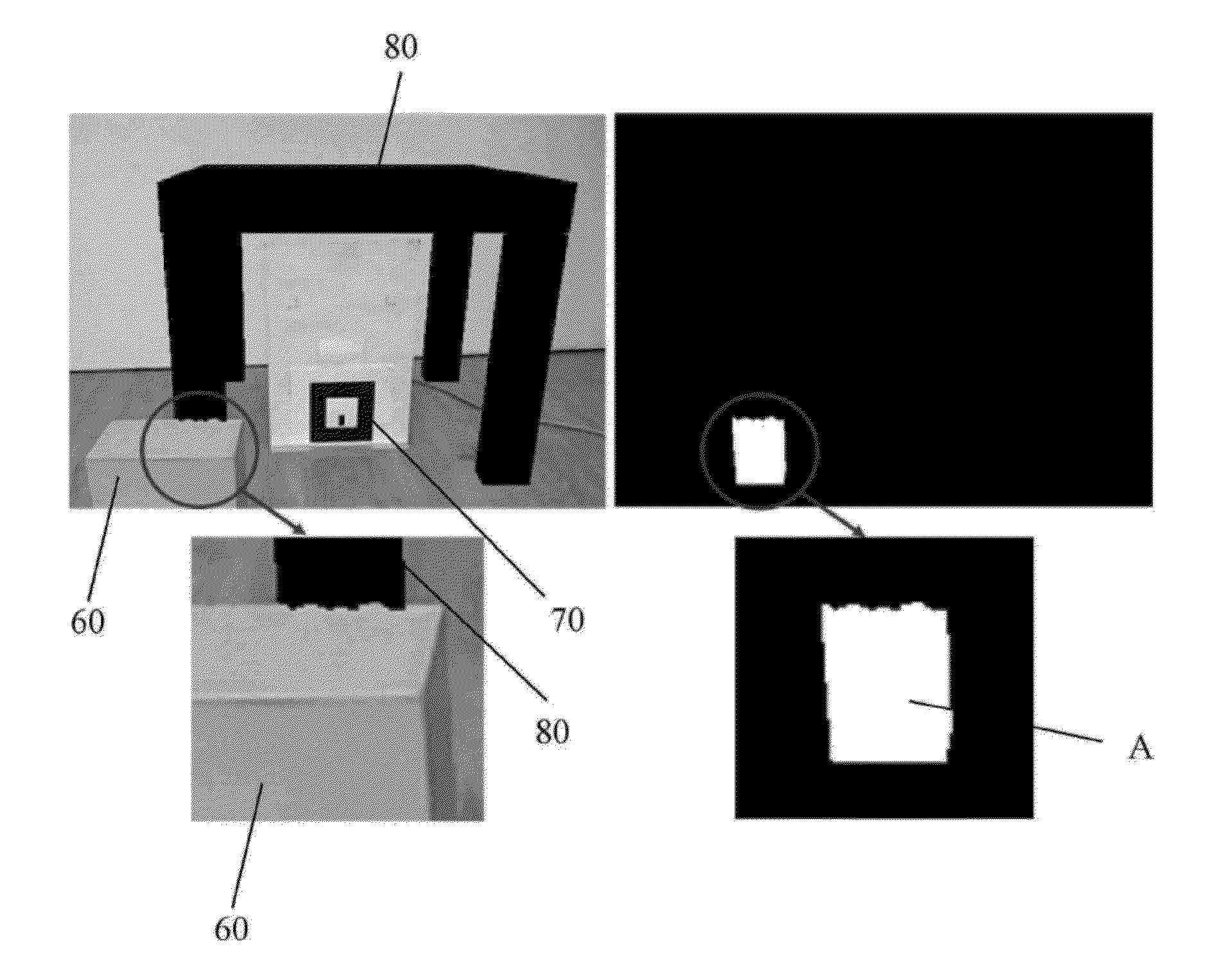
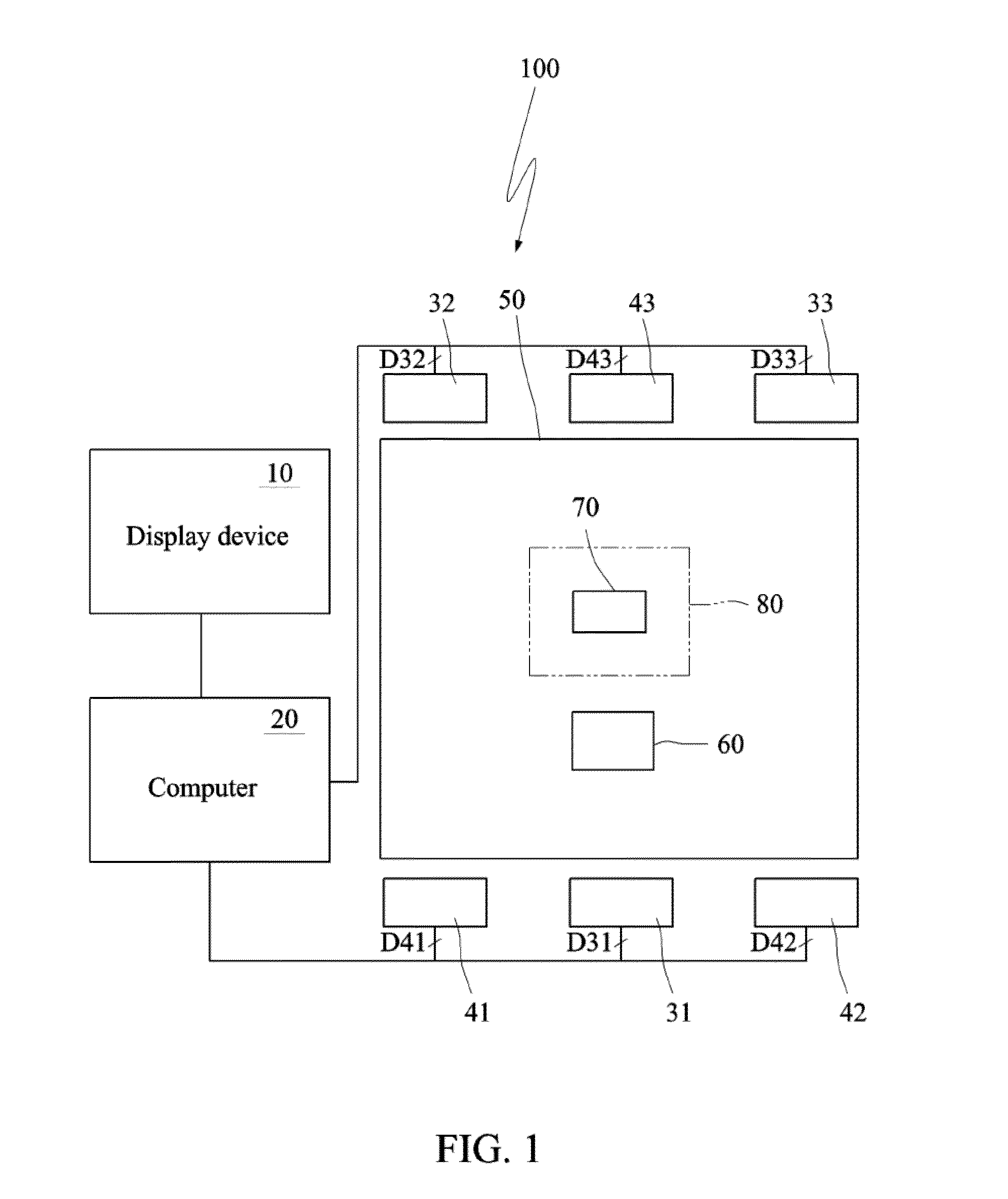
[0021]FIG. 1 is a schematic view showing a system using a method for optimizing occlusion according to a preferred embodiment of the invention. FIG. 2 is a flow chart showing the method for optimizing occlusion according to the preferred embodiment of the invention. Referring to FIGS. 1 and 2, the method for optimizing occlusion in augmented reality based on depth cameras according to the embodiment of the invention is applied to an augmented reality system 100. The augmented reality system 100 comprises one or multiple depth cameras (three depth cameras 41, 42 and 43 are depicted), and one or multiple color cameras (three color cameras 31, 32 and 33 are depicted). In addition, the augmented reality system 100 may further comprise a computer 20 and a display device 10. The computer 20...


PUM


Abstract

A method for optimizing occlusion occurring in an augmented reality system comprising a depth camera and a two-dimensional camera comprises the steps of: capturing, by a depth camera, a scene and an object in the scene to obtain initial depth data, and capturing, by the two-dimensional camera, the scene and the object to obtain two-dimensional image data; in-painting the initial depth data to obtain in-painted depth data; performing a depth buffer calculation according to the in-painted depth data and a virtual model to obtain an occlusion relationship between the object and the virtual model, and generating an occluded partial image according to the two-dimensional image data and the virtual model; estimating partially approximated polygon according to the occluded partial image; and generating an occluded result according to the partially approximated polygon, the two-dimensional image data and the virtual model.

Description

This application claims priority of No. 104101890 filed in Taiwan R.O.C. on Jan. 21, 2015 under 35 USC 119, the entire content of which is hereby incorporated by reference.BACKGROUND OF THE INVENTION[0001]1. Field of the Invention[0002]The invention relates to a method for optimizing occlusion, and more particularly to a method for optimizing occlusion in augmented reality based on depth cameras.[0003]2. Related Art[0004]Recently, depth sensing technologies have been successfully applied to various industries. For example, the entertainment industry has developed novel man-machine interaction functions based on human body tracking and motion recognition enabled by depth cameras. A common principle of depth sensing is to emit infrared light to the target scene and thus to generate laser speckle patterns on the objects in the scene. Then, the laser speckle data is obtained through a sensing lens and the depth values are calculated. When the infrared light is projected onto an object i...

Claims


Application Information

Patent Timeline
Patent Type & Authority Applications(United States)
IPC IPC(8): G06T19/00G06T13/20G06T15/40
CPCG06T19/006G06T2215/16G06T13/20G06T15/405
Inventor CHU, CHIH-HSINGHUANG, PO-YUAN
Owner NATIONAL TSING HUA UNIVERSITY
Learn More