IoT communications bridging power switch

a power switch and iot technology, applied in the field of remote communication with electronic devices, can solve the problems of limiting the placement of devices, and limiting the ability of devices to communicate with each other, so as to reduce the number of devices, increase the flexibility of their placement, and increase the flexibility of power consumption

Active Publication Date: 2016-07-21
HUBBELL INC
View PDF31 Cites 71 Cited by
  • Summary
  • Abstract
  • Description
  • Claims
  • Application Information

AI Technical Summary

Benefits of technology

The invention allows for a smaller number of devices to be connected to a wireless network, making it more efficient. Additionally, devices connected to the network can communicate with other wireless devices through a bridging function, without needing to connect directly. This increases flexibility in device placement, usage, power sources, and power consumption. The invention also allows for a power switch to control power delivery based on information from another wireless device, without needing a direct connection.

Problems solved by technology

Often, these types of communication are not readily adaptable to each other or a common user interface.
This can limit the ability of devices to communicate with each other.
This may require limitations on where the devices may be placed, where the router may be placed, or require multiple routers or other wireless access points.
In addition, this proximity requirement may limit the type of wireless communication available for connecting between the device and the wireless network.
However, Wi-Fi may require an undesirable power requirement.
This may be an issue where the wireless device is not permanently connected to a power source and is powered by a battery, either disposable or rechargeable.
However, Bluetooth technology has a limited range that renders it unsuitable for longer distance communication.
Thus, Bluetooth protocol may be desired for the particular application, but it may not be practical due to the range limitations.

Method used


Image

  • IoT communications bridging power switch
  • IoT communications bridging power switch
  • IoT communications bridging power switch

Examples


Embodiment Construction

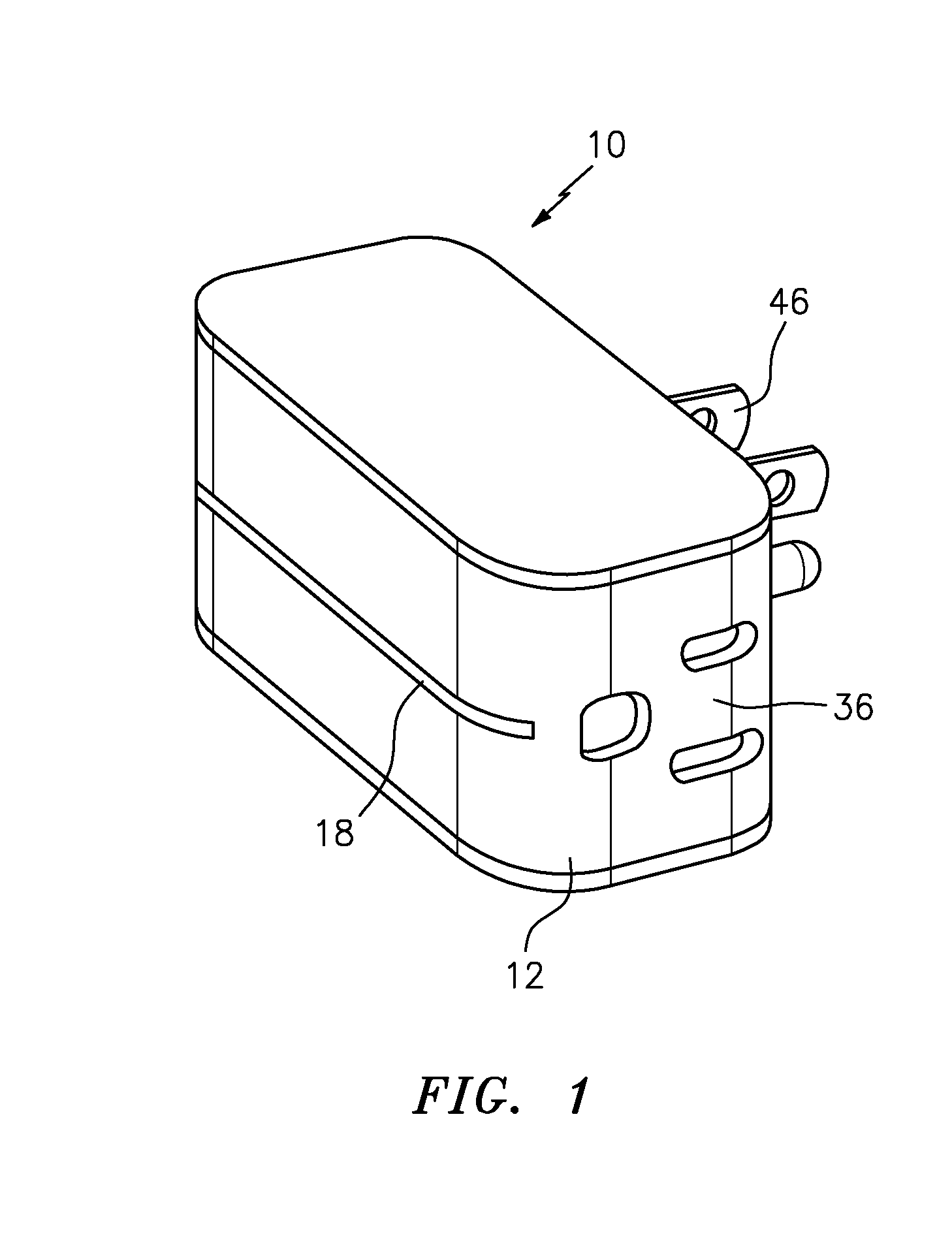
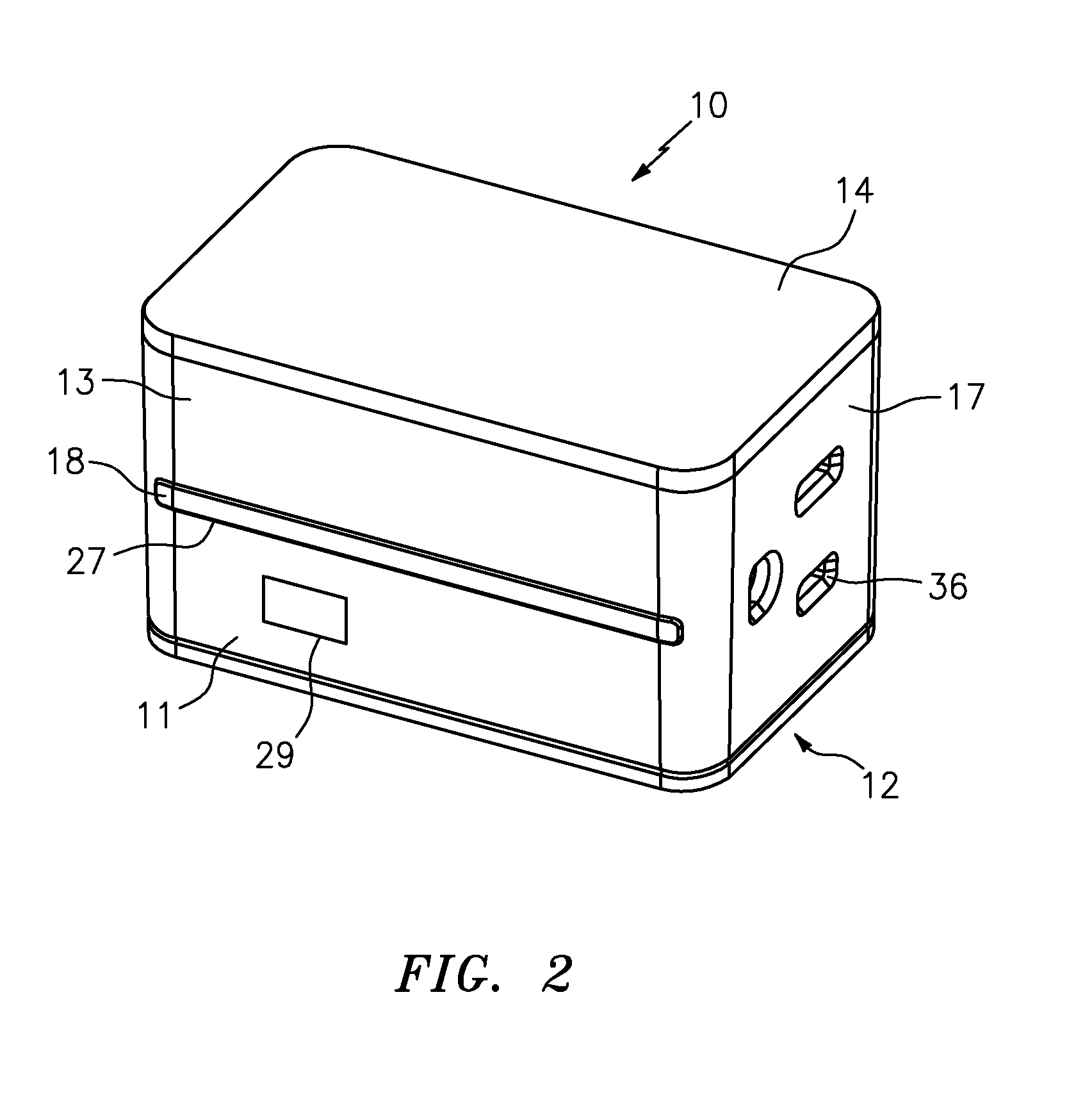
[0036]FIGS. 1 and 2 show an embodiment of power switching device 10. Switching device 10 has a housing or enclosure 12 enclosing the internal components of the power switching device 10, a status indicator 18, a power receptacle 36, and a power connector 46.

[0037]Referring to FIG. 2, the embodiment of FIG. 1 is shown in further detail. The power switching device 10 is encased by a housing 12, which includes a casing 11 substantially laterally surrounding the internal components of the plug and to which is attached, e.g., snap fit into, a top cover 14 and a bottom cover 16. In the embodiment shown, casing 11, top cover 14, and bottom cover 16 form a substantially brick-like shape. The longest axis of the substantially brick-like shape is oriented in a horizontal direction when the plug is inserted into a typically oriented electrical socket in the United States. This orientation is advantageous in that it enables the power switching device 10 to fit compactly within the vertical spac...


PUM


Abstract

Power switching devices deliver power to at least one powered device and may command, control and / or monitor the powered device(s). The power switching devices may further bridge communications between remote devices, and for wireless devices uses wireless communication, such as, but not limited to, radio frequency (RF), Bluetooth, light, and sound frequencies, and Wi-Fi, wired and wireless internet, the cloud, and personal computing devices. Systems utilize such power switching devices for monitoring, command and / or control of the remote or powered devices, integration of information into data management applications, data storage, putting into place threshold alarms, monitoring available variables, functions and data, and associating events with time.

Description

CROSS-REFERENCE TO RELATED APPLICATIONS[0001]This application claims benefit under 35 U.S.C. §119(e) to United States Provisional Patent Application No. 62 / 100,000, filed Jan. 5, 2015, which is incorporated herein by reference in its entirety and made a part hereof.FIELD OF THE DISCLOSURE[0002]The present disclosure relates generally to remote communication with electronic devices. More specifically, the present disclosure relates to power switches that are equipped with modules for multiple modes of remote communication and are thereby capable of serving as a bridge between connected electronic devices. In addition, the present disclosure relates to methods of remote communication with electronic devices using a power switch equipped with multiple modes of remote communication.BACKGROUND INFORMATION[0003]Internet of Things (IoT) technology has led to a plethora of computing devices to remotely automate, control, and monitor powered devices. There are many types of data communicatio...

Claims


Application Information

Patent Timeline
Patent Type & Authority Applications(United States)
IPC IPC(8): G06F1/26H04L29/08H04L12/12
CPCG06F1/266H04L67/125H04L12/12H04L12/2823H04L2012/2841H04W4/80H04L41/04G06F1/3203
Inventor BRANTNER, PAULTETREAULT, MICHAELFERGUSON, ERICDAVIS, DAVIDMONTEITH, SHAWNMURRAY, MICHAELDJAKOVIC, VLADAN
Owner HUBBELL INC
Why Eureka
Try Eureka