
Single particulate metering system with variable rate controls

a metering system and variable rate technology, applied in the direction of machines/engines, process and machine control, instruments, etc., can solve the problems of metering implements that cannot meet the requirements of upstream air pressure, metering implements can experience wall friction, and can generate sufficient airflow

Active Publication Date: 2016-07-21
MONTAG INVESTMENTS
View PDF2 Cites 20 Cited by
  • Summary
  • Abstract
  • Description
  • Claims
  • Application Information

AI Technical Summary

Benefits of technology

The present patent provides a particulate metering system with variable application rate controls for separate discharges or a group of discharges. The system includes an air flow origin, a plurality of particulate accelerators, and a plurality of operated conveyances. The particulate accelerators have an air-particulate interface, a mixing area, and an air-particulate output. The system also includes a particulate storage area and a discharge line connected to the air-particulate output of each particulate accelerator. The operated conveyances convey particulate from the particulate storage areas to the particulate accelerators. The system can operate at different rates and can include one or more motors and cartridges. The technical effects of the patent include the ability to control the rate of particulate conveyed to the confluence, the ability to control the distribution of particulate across the particulate accelerators, and the ability to control the speed and rate of operation of the operated conveyances.

Problems solved by technology

Therefore, complications can arise generating sufficient airflow to meter particulate to all of the row units while controlling the application rates.
Still further, the particulate traveling through an airflow path of the metering implement can experience wall friction, requiring greater upstream air pressure and increased power consumption to meter the particulate at desired application rates.
Losses and frictional effects within the system also increase the likelihood of lag and clogging.

Method used


Image

  • Single particulate metering system with variable rate controls
  • Single particulate metering system with variable rate controls
  • Single particulate metering system with variable rate controls

Examples


Embodiment Construction

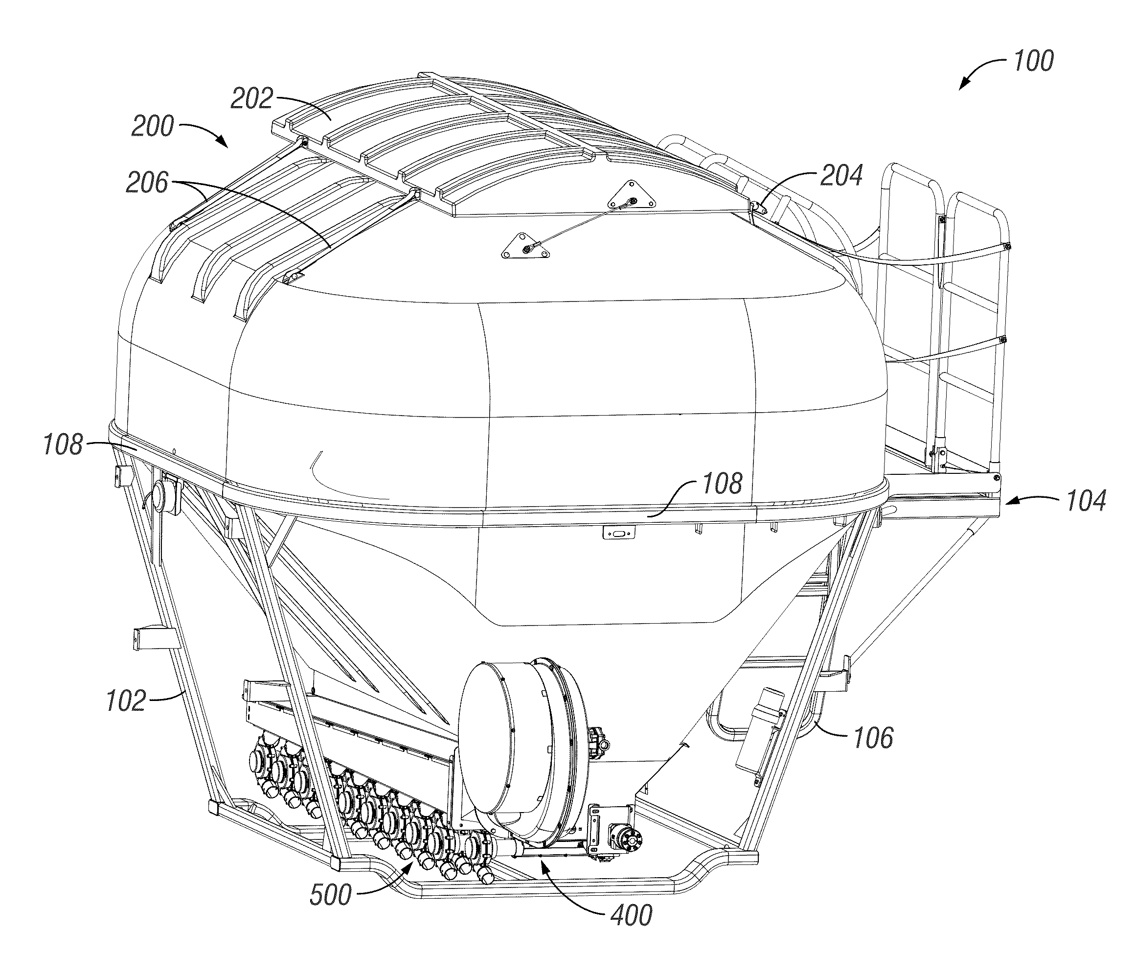
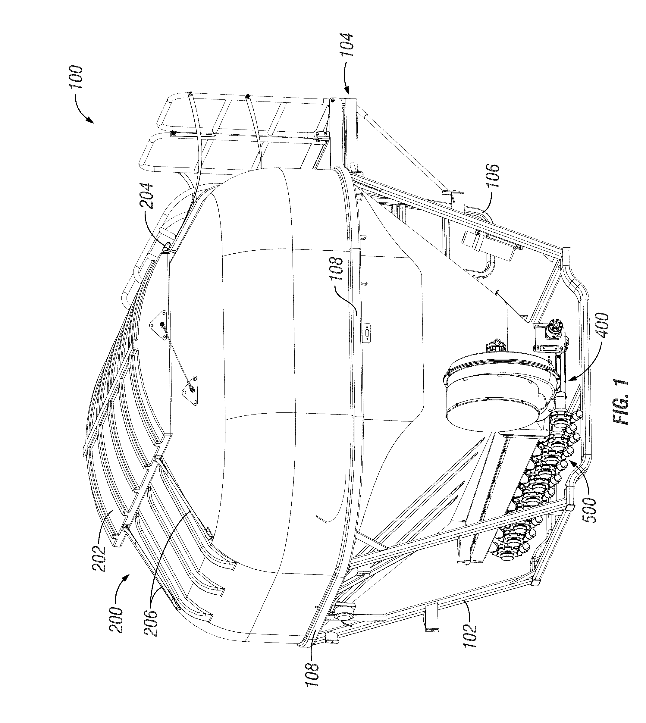
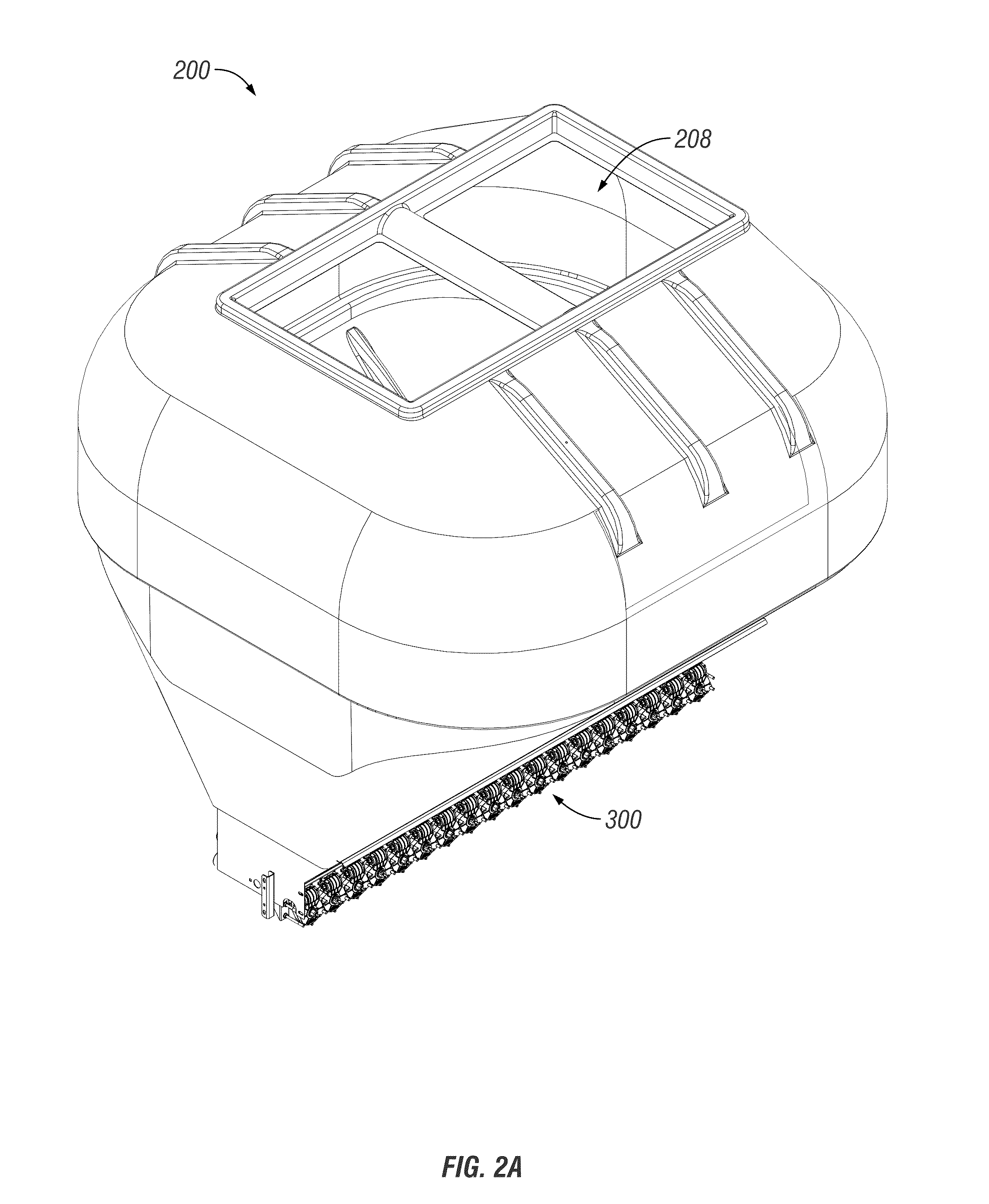
[0034]FIG. 1 shows a particulate metering implement 100. While the figure shows a particulate metering implement, it should be appreciated by those skilled in the art that the disclosure covers other types of implements, including but not limited to, seed meters, seed planters, nutrient applicators, and other agricultural equipment. The implement 100 can be mounted upon a towable trailer or other suitable structure such as a toolbar, or integrally formed with a particulate application system. The implement can include a frame assembly 102, upon which a particulate container 200 is disposed. For user accessibility to the particulate container 200, a platform 104 and a ladder 106 can be provided. The implement can also include a particulate handling system 300 (FIG. 2A), an air production and handling system 400, and particulate accelerator system 500.

[0035]In an embodiment, the implement can include a second particulate handling system 300, a second air production and handling system...


PUM


Abstract

An improved particulate metering system is provided. The system includes an air flow origin and a plurality of particulate accelerators. A single particulate source is in communication with the particulate accelerators. Each of a plurality of operated conveyances can be in operable communication with the single particulate source and one of the particulate accelerators. The system includes a confluence of the air flow and the particulate within the mixing area of each of the particulate accelerators. Each of a plurality of discharges can be associated with the particulate accelerators. The operated conveyances can operate at different rates. The system can include one or more gearboxes adapted to be inverted and controlled by a second drive system. The improved system and controls provide variable application rates of particulate across rows in a field.

Description

BACKGROUND[0001]I. Field of the Disclosure[0002]A metering system for solid particulate is disclosed. More specifically, but not exclusively, a metering system with variable application rate controls for particulate matter, such as dry fertilizers, is disclosed.[0003]II. Description of the Prior Art[0004]Particulate metering systems use varied approaches to control the rate at which particulate is metered. In such instances where the particulate is fertilizer, there's a significant interest in controlling the application rate of the fertilizers, and specifically controlling the application rate across separate rows in a field. In other words, what is desired in at least one application is a dry fertilizer metering system that can adjust or vary the application rate on a row-by-row basis—one row receiving fertilizer(s) at a desired rate while another row receives fertilizer(s) at the same or another desired rate. In most instances of multi-row metering using pneumatics, the distance ...

Claims


Application Information

Patent Timeline
Patent Type & Authority Applications(United States)
IPC IPC(8): A01C15/04A01C15/00G01F11/00
CPCA01C15/04A01C15/003A01C15/005G01F11/003A01C7/082A01C7/16G01F13/005G05D7/0605G05D11/132A01C7/102A01C7/081A01C15/16A01C19/02Y02P60/21G05D7/00A01C15/006A01C15/12F04D25/08
Inventor MONTAG, ROGER A.MOGLER, ISAACFEHR, JASON
Owner MONTAG INVESTMENTS
Learn More