


Quick Research
Generate reliable direction feasibility study reports for your R&D in just a few steps.

Technical Q&A
Discover and master advanced knowledge NOW. Basics, ideas, possibilities, all at once.

Find Solutions
As an expert in R&D theories, this can generate solutions to your technical problems instantly.

Evaluate Feasibility
Analyze your overall solution with one click, know your potential R&D risks in advance.

Monitor Landscape
Get weekly tech updates, stay abreast of the latest tech innovations and key insights.
Hydraulic braking system
a technology of hydraulic braking and braking components, applied in the direction of braking systems, braking components, transportation and packaging, etc., can solve the problems of reducing the accuracy of control of slip control devices, and achieve the effect of suppressing vibrations of hydraulic pressur
- Summary
- Abstract
- Description
- Claims
- Application Information
AI Technical Summary
Benefits of technology
Problems solved by technology
Method used
Image

Examples
first embodiment
Configuration of Hydraulic Braking System
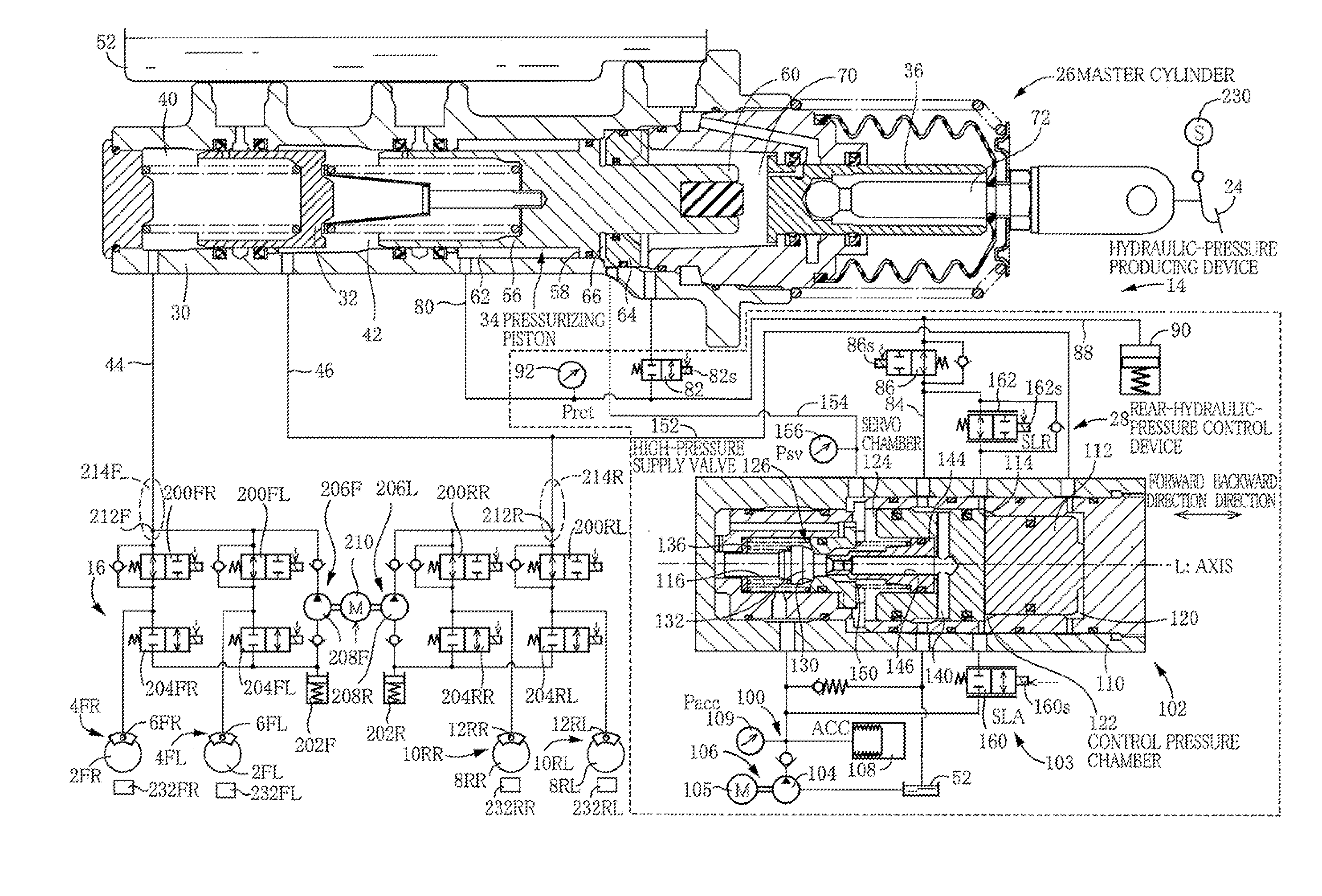
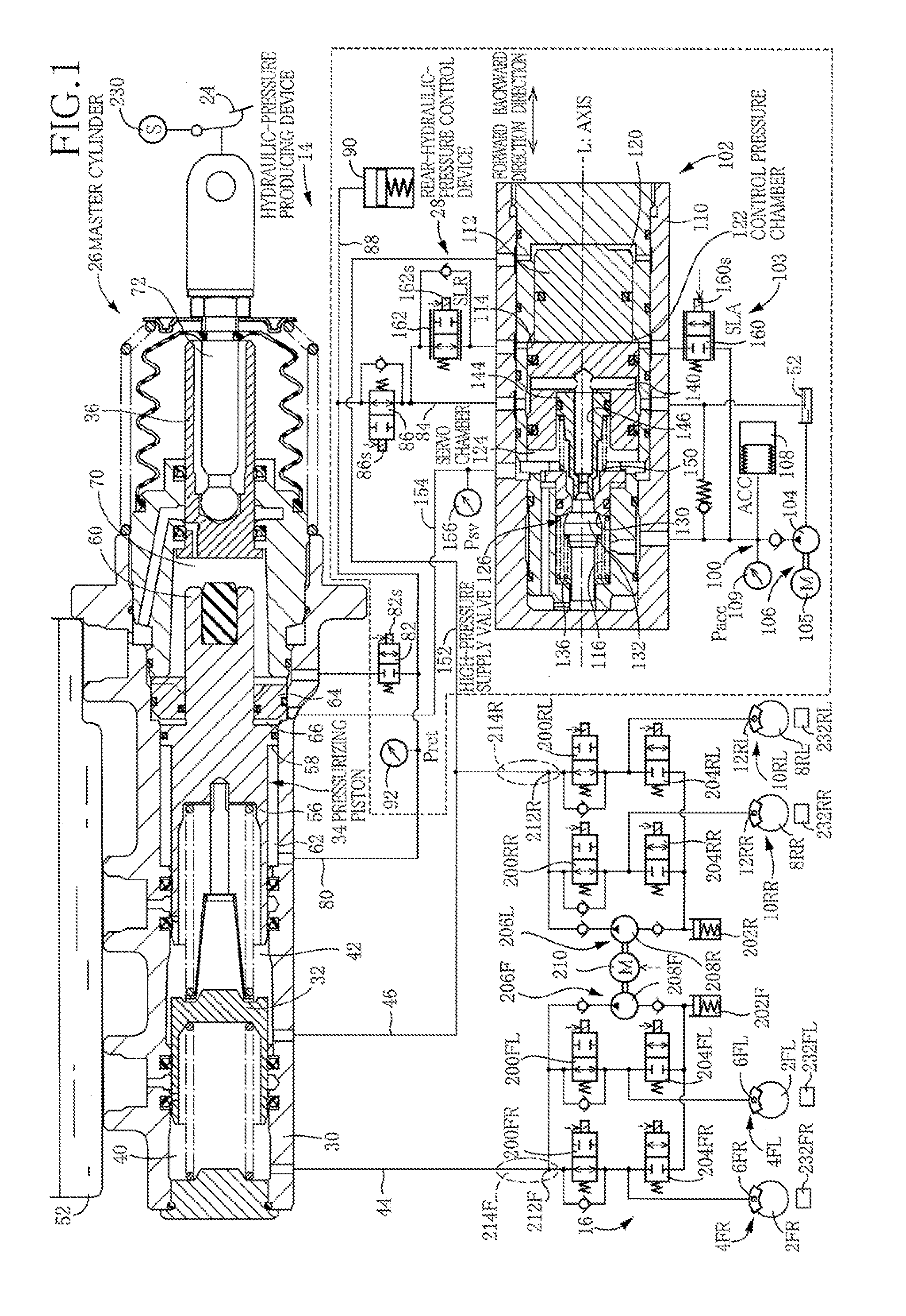
[0146]As illustrated in FIG. 1, the hydraulic brake system includes (i) brake cylinders 6FL, 6FR of hydraulic brakes 4FL, 4FR respectively provided for front left and right wheels 2FL, 2FR, and brake cylinders 12RL, 12RR of hydraulic brakes 10RL, 10RR respectively provided for rear left and right wheels 8RL, 8RR, (ii) a hydraulic-pressure producing device 14 capable of supplying a hydraulic pressure to these brake cylinders 6FL, 6FR, 12RL, 12RR, and (iii) a slip control device 16 provided between the hydraulic-pressure producing device 14 and the brake cylinders 6FL, 6FR, 12RL, 12RR. Devices such as the hydraulic-pressure producing device 14 and the slip control device 16 are controlled by a brake ECU 20 (see FIG. 4) constituted mainly by a computer.
[0147][Hydraulic-Pressure Producing Device]
[0148]The hydraulic-pressure producing device 14 includes (i) a brake pedal 24 as a brake operating member, (ii) a master cylinder 26, (iii) a rear-hydra...
second embodiment
[0243]The hydraulic braking system may be configured as illustrated in FIG. 10. In the hydraulic braking system according to the present embodiment, the hydraulic pressure in the rearward chamber 66 is directly controlled by control for the pressure-increase linear valve and the pressure-reduction linear valve. It is noted that the same reference numerals as used in the first embodiment are used to designate the corresponding elements of this embodiment, and an explanation of which is dispensed with.
[0244]In the present hydraulic braking system, a rear-hydraulic-pressure control device 250 is connected to the rearward chamber 66. The rear-hydraulic-pressure control device 250 does not include the regulator but includes the high pressure source 100 and a linear valve device 252. The linear valve device 252 includes: a pressure-increase linear valve 254 as a rearward chamber pressure-increase linear valve provided between the high pressure source 100 and the rearward chamber 66; and a...
third embodiment
[0248]The hydraulic braking system may be configured as illustrated in FIG. 11. It is noted that the same reference numerals as used in the first and second embodiments are used to designate the corresponding elements of this embodiment, and an explanation of which is dispensed with.
[0249]The present hydraulic braking system has front and rear lines. A master cylinder 300 includes two pressurizing pistons 302, 303. Front pressure chambers 304, 305 are defined in front of the respective pressurizing pistons 302, 303. The brake cylinders 6 for the front left and right wheels and the brake cylinders for the rear left and right wheels are connected to the respective front pressure chambers 304, 305 via respective master passages 306, 307. FIG. 11 illustrates brake lines for the front wheels but omits illustration of brake lines for the rear wheels.
[0250]A slip control device 310 is provided between the front pressure chamber 304 and the brake cylinders 6FL, FR of the respective front le...
PUM
 Abstract
Description
Claims
Application Information
 - R&D Engineer
- R&D Manager
- IP Professional
- Industry Leading Data Capabilities
- Powerful AI technology
- Patent DNA Extraction
Browse by: Latest US Patents, China's latest patents, Technical Efficacy Thesaurus, Application Domain, Technology Topic, Popular Technical Reports.
© 2024 PatSnap. All rights reserved.Legal|Privacy policy|Modern Slavery Act Transparency Statement|Sitemap|About US| Contact US: help@patsnap.com