
Droplet evaporation based self-cleaning humidification device

a self-cleaning, droplet technology, applied in the field of humidifiers, can solve the problems of ultrasonic humidifiers, fatal to health, and significant increase of alternative product markets, such as charcoal and natural evaporation devices

Active Publication Date: 2016-06-30
FEMTOBIOMED INC
View PDF2 Cites 3 Cited by
  • Summary
  • Abstract
  • Description
  • Claims
  • Application Information

AI Technical Summary

Benefits of technology

The present invention is a humidifier that solves disadvantages of conventional humidifiers by evaporating vapor and supplying it to the air without the need for separate cleaning. Additionally, harmful materials are collected by the final falling water and discarded. It is safer than conventional humidifiers as it does not spray floating drops that can cause accidents or molds. As a result, it is more efficient and safe for use.

Problems solved by technology

In particular, alternate product markets, such as charcoal and natural evaporation devices, are significantly increased due to chronic problems and inconvenience, such as a safety problem and the difficulty of cleaning and management in existing humidification apparatuses.
A direct spray method, such as an ultrasonic humidification method, is advantageous in that maintenance is relatively easy because residues rarely remain in a humidification module and power consumption is low, but is problematic in that health it may be fatal to health because compounds of calcium, heavy metals and / or virus remaining in water is introduced into air.
Such materials are used for various products, such as shampoo and water tissues, because they have skin toxicity which is about 1 of a 5˜10 percentage point compared to other germicides, but no sanction was not applied to the materials until victims were generated because research had not been carried out on toxicity generated when the materials were inhaled by a respiratory organ.
In U.S.A., Europe, and China in which many compounds of calcium is present in tap water, the problem of the ultrasonic humidifier has already come to the fore because compounds of calcium included in water are sprayed into air in a fine dust form apart from the germicide problem.
However, the heating type humidifier is very inconvenient because residues in water adhere to a heating plate after pure water is supplied and thus the heating plate must be periodically cleaned.
In particular, if many compounds of calcium are included in tap water as in U.S.A., Europe, and China, solid compounds of calcium are thickly deposited on the heating plate even after use of several days, and it is very inconvenient to remove the compounds of calcium deposited on the heating plate.
However, such a kind of humidifier has disadvantages in that a stack structure of several tens of disks for widening a surface area of an evaporation plate makes it difficult cleaning and maintenance and the amount of humidification is relatively low.
In order to supplement such disadvantages, strong air circulation needs to be generated using a fan, which may lead to a noise problem.
There is an evaporation type humidifier using a disposable module without using the evaporation disks due to the difficulty of such cleaning.
All of existing humidification apparatuses on the market do not satisfy both the core elements “safety” and “cleaning and maintenance.”

Method used


Image

  • Droplet evaporation based self-cleaning humidification device
  • Droplet evaporation based self-cleaning humidification device
  • Droplet evaporation based self-cleaning humidification device

Examples


first embodiment

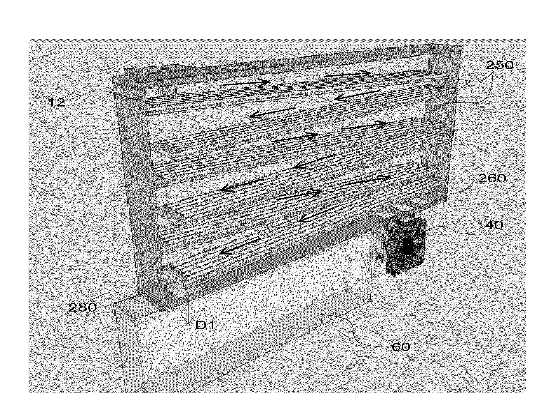
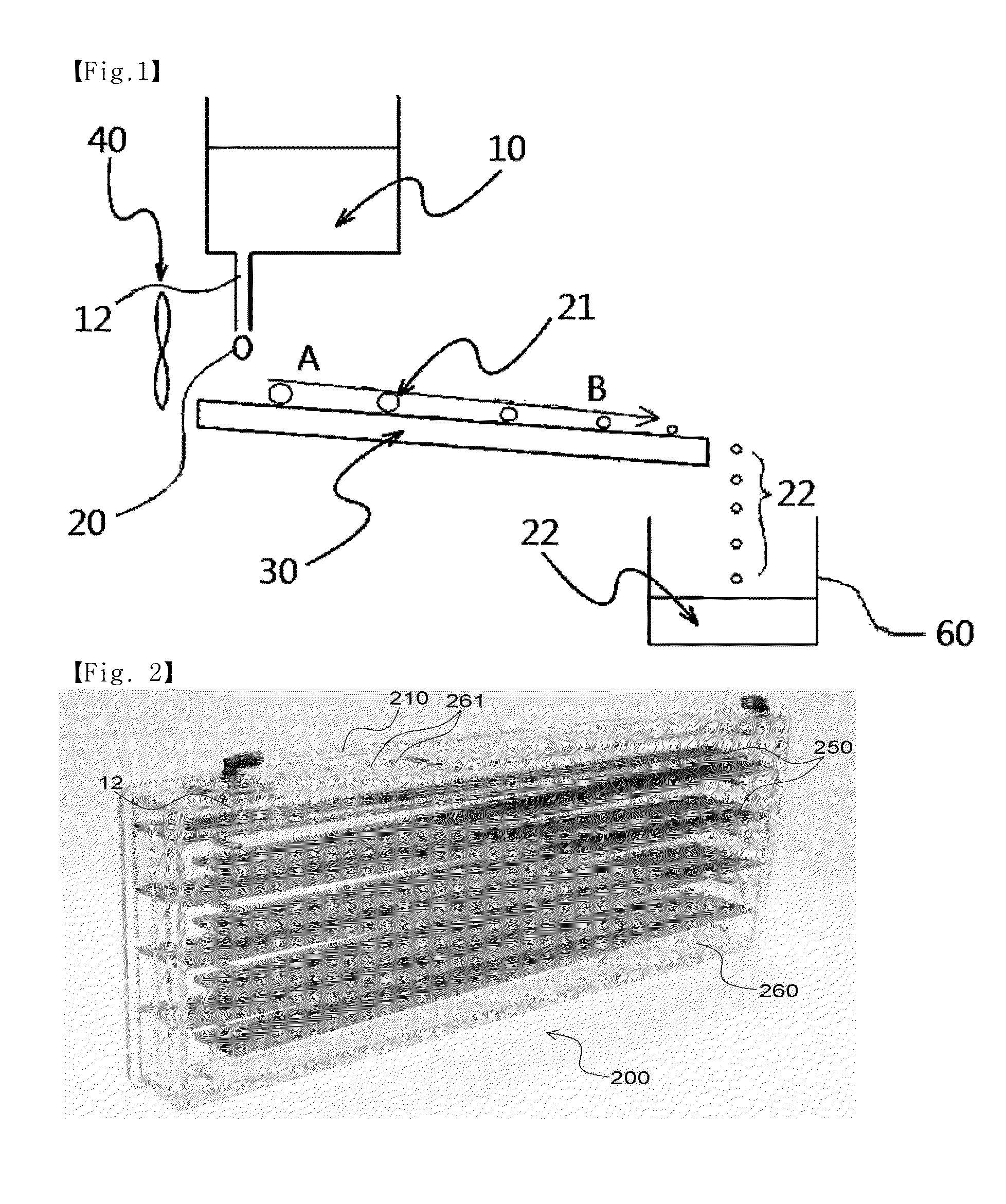
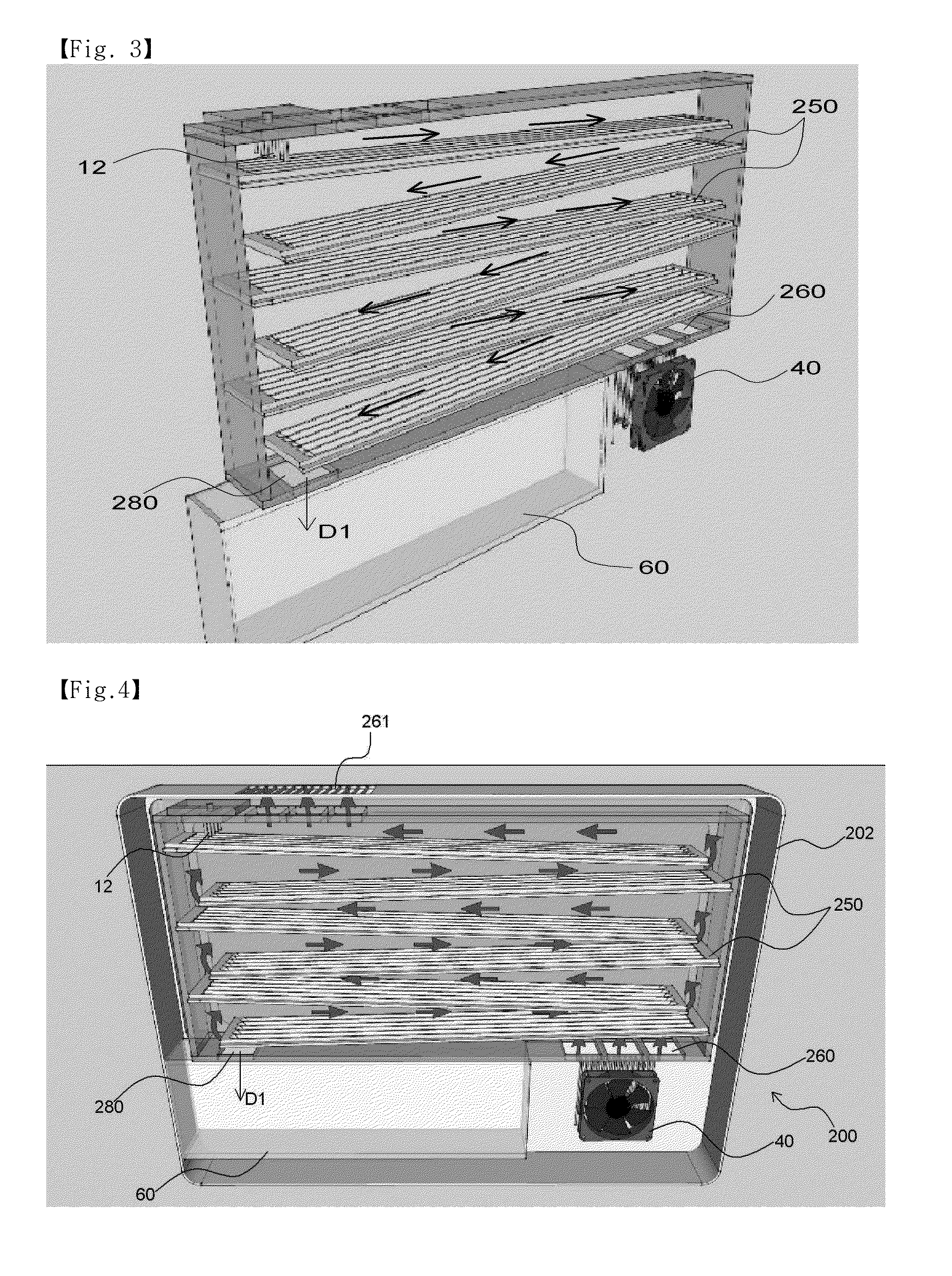
[0048]FIGS. 2 to 5 are diagrams related to the first embodiment. A step type humidifier 200 includes the evaporation plate 250 having multi-staged plates formed on a horizontal surface at a specific angle. The nozzle 12 for supplying water is installed on one side of an evaporation plate 250 at the top layer. Furthermore, a collection container 260 for collecting the falling water is formed at the bottom of the housing. The water tank is omitted, for convenience sake.

[0049]Means for accelerating the evaporation of floating drops moving on the evaporation plate 250 may be a heater for heating the evaporation plate 250, a fan for forcedly moving air around the surface of the evaporation plate 250, an infrared radiation device or microwave radiation device for supplying radiation heat to the water on the surface of the evaporation plate 250, or a combination of two or more of them.

[0050]Water supplied by the nozzle 12 goes down in zigzags along the inclined evaporation plate 250. Vapor...

second embodiment

[0058]The present embodiment has a form, such as the evaporation plate 310 shown in FIGS. 6 to 8.

[0059]FIG. 8 is a side view of the humidifier, and FIG. 7 shows that floating drops actually flow on the evaporation plate 310.

[0060]The humidifier of the present embodiment may be called a spiral type and has a structure in which floating drops flow down along a curved surface of a spiral form from top to bottom. Such a structure has advantages in that a narrow space can be used, the path of floating drops moving on the surface of the evaporation plate can be increased, and a unique and beautiful appearance can be obtained.

[0061]The moving water 21, that is, water supplied through a water supply pipe 320 and the nozzle 12, flows down while rotating on the surface of the evaporation plate 310 in an R direction. The size of floating drops is gradually reduced as the moisture components of the water are evaporated, and the floating drops finally fall through a water outlet 380 placed at th...

third embodiment

[0064]FIG. 9 shows another example of the evaporation plate according to the third embodiment. The evaporation plate 410 according to the third embodiment is basically similar to that of the second embodiment. The diameter of the evaporation plate 410 according to the present embodiment is not reduced, but the evaporation plate 410 is formed in a track type and has a structure in which short-distance athletics tracks overlap in several layers.

[0065]The track type is advantageous in that the water tank can be installed in the empty space at the center of the evaporation plate 410 and the moisture components of floating drops can be sufficiently evaporated because the moving path of moving water is increased on the same width condition compared to the spiral type.

[0066]Water supplied by the humidification apparatus according to the embodiments of the present invention may be applied to both a floating drop form and a flowing water form.


PUM

PropertyMeasurementUnit
evaporation accelerationaaaaaaaaaa
gravityaaaaaaaaaa
humidityaaaaaaaaaa

Abstract

Disclosed herein is a self-cleaning evaporation type humidification apparatus. The self-cleaning humidification apparatus is a floating drop evaporation type humidification apparatus of a new concept using a super hydrophobic surface, which provides safe humidification and does not require maintenance and repair, such as cleaning, by naturally or forcedly evaporating floating drops through control of the floating drops in the super hydrophobic surface based on the self-cleaning function, virus reproduction inhibition function, and water-repellant function of the super hydrophobic surface.

Description

CROSS-REFERENCE TO RELATED APPLICATIONS[0001]This application is the U.S. National Phase of International Application No. PCT / KR2014 / 007071, filed Jul. 31, 2014, which claims the benefit of Korea Patent Application No. 10-2013-0090559, filed Jul. 31, 2013, the disclosures of which are incorporated herein by reference.TECHNICAL FIELD[0002]The present invention relates to a humidifier capable of self-cleaning and, more particularly, to a humidifier technology in which a self-cleaning function has been implemented through a super water-repellant induction phenomenon or a super water-repellant coating surface based on a technology for evaporating and controlling floating drops.BACKGROUND ART[0003]A humidification apparatus having control of humidity as a main function is required for a pleasant life of the human being and is essential to prevent a variety of types of diseases and to maintain health. In Korea, the volume of a household humidifier market approaches 100 billons won, and th...

Claims


Application Information

Patent Timeline
Patent Type & Authority Applications(United States)
IPC IPC(8): F24F6/10F24F6/04
CPCF24F6/105F24F6/04F24F6/10F28F19/00F28F2245/04F24F6/02B01F23/20
Inventor LEE, SANGHYUN
Owner FEMTOBIOMED INC
Learn More